Custom Search
|
|
  |
|
|
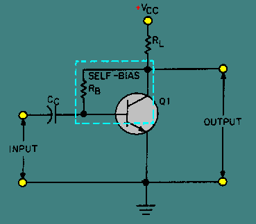
TYPES OF BIAS One of the basic problems with transistor amplifiers is establishing and maintaining the proper values of quiescent current and voltage in the circuit. This is accomplished by selecting the proper circuit-biasing conditions and ensuring these conditions are maintained despite variations in ambient (surrounding) temperature, which cause changes in amplification and even distortion (an unwanted change in a signal). Thus a need arises for a method to properly bias the transistor amplifier and at the same time stabilize its dc operating point (the no signal values of collector voltage and collector current). As mentioned earlier, various biasing methods can be used to accomplish both of these functions. Although there are numerous biasing methods, only three basic types will be considered. Base-Current Bias (Fixed Bias) The first biasing method, called BASE CURRENT BIAS or sometimes FIXED BIAS, was used in figure 2-12. As you recall, it consisted basically of a resistor (RB) connected between the collector supply voltage and the base. Unfortunately, this simple arrangement is quite thermally unstable. If the temperature of the transistor rises for any reason (due to a rise in ambient temperature or due to current flow through it), collector current will increase. This increase in current also causes the dc operating point, sometimes called the quiescent or static point, to move away from its desired position (level). This reaction to temperature is undesirable because it affects amplifier gain (the number of times of amplification) and could result in distortion, as you will see later in this discussion. Self-Bias A better method of biasing is obtained by inserting the bias resistor directly between the base and collector, as shown in figure 2-13. By tying the collector to the base in this manner, feedback voltage can be fed from the collector to the base to develop forward bias. This arrangement is called SELF-BIAS. Now, if an increase of temperature causes an increase in collector current, the collector voltage (VC) will fall because of the increase of voltage produced across the load resistor (RL). This drop in VC will be fed back to the base and will result in a decrease in the base current. The decrease in base current will oppose the original increase in collector current and tend to stabilize it. The exact opposite effect is produced when the collector current decreases. Figure 2-13. - A basic transistor amplifier with self-bias.
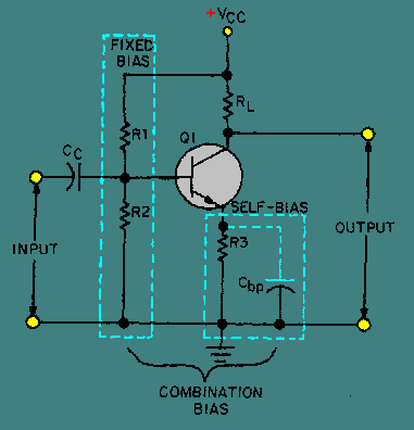
Self-bias has two small drawbacks: (1) It is only partially effective and, therefore, is only used where moderate changes in ambient temperature are expected; (2) it reduces amplification since the signal on the collector also affects the base voltage. This is because the collector and base signals for this particular amplifier configuration are 180 degrees out of phase (opposite in polarity) and the part of the collector signal that is fed back to the base cancels some of the input signal. This process of returning a part of the output back to its input is known as DEGENERATION or NEGATIVE FEEDBACK. Sometimes degeneration is desired to prevent amplitude distortion (an output signal that fails to follow the input exactly) and self-bias may be used for this purpose. A combination of fixed and self-bias can be used to improve stability and at the same time overcome some of the disadvantages of the other two biasing methods. One of the most widely used combination-bias systems is the voltage-divider type shown in figure 2-14. Fixed bias is provided in this circuit by the voltage-divider network consisting of R1, R2, and the collector supply voltage (VCC). The dc current flowing through the voltage-divider network biases the base positive with respect to the emitter. Resistor R3, which is connected in series with the emitter, provides the emitter with self-bias. Should IE increase, the voltage drop across R3 would also increase, reducing VC. This reaction to an increase in IE by R3 is another form of degeneration, which results in less output from the amplifier. However, to provide long-term or dc thermal stability, and at the same time, allow minimal ac signal degeneration, the bypass capacitor (Cbp) is placed across R3. If Cbp is large enough, rapid signal variations will not change its charge materially and no degeneration of the signal will occur. Figure 2-14. - A basic transistor amplifier with combination bias.
In summary, the fixed-bias resistors, R1 and R2, tend to keep the base bias constant while the emitter bias changes with emitter conduction. This action greatly improves thermal stability and at the same time maintains the correct operating point for the transistor. Q.18 Which biasing method is the most unstable? |
 |