Custom Search
|
|
  |
|
|
For a sweep generator that produces a more linear output sawtooth waveform, refer to the circuit in figure 3-45, view (A). R1 and C1 form the RC time constant. Notice that the capacitor charges toward 35 volts (VE) in this circuit. Figure 3-45A. - Improved unijunction sawtooth generator.
Figure 3-45B. - Improved unijunction sawtooth generator.
The output waveform is shown in figure 3-45, view (B). With a lower voltage applied from B1 to B2, the peak and valley points are closer together. Calculating the percentage of charge:
The linearity in this case is good. Using the Universal Time Constant Chart, a 10-percent charge amounts to 0.1 time constant. The electrical length is, again, RC times the number of time constants. With R1 at 300 kilohms and C1 at .005 microfarads, the time constant is 1,500 microseconds. One-tenth of a time constant is equal to 150 microseconds; so the electrical length is 150 microseconds. Prt is the electrical length plus the fall or flyback time. If C1 discharges from 5.3 volts to 2 volts in 15 microseconds, then the prt is 150 + 15, or 165 microseconds. The prf is about 6 kilohertz
Some unijunction circuits are triggered to obtain a very stable prf. One method is to apply triggers to B2, as shown in figure 3-46. Negative triggers applied to B2 reduce the inter-base voltage enough to cause a forward bias condition in the emitter circuit. This cuts off the sweep and allows C1 to discharge through the B1-to-emitter circuit. Then, C1 recharges until the next trigger arrives and C1 discharges. Circuit operation and parameters are figured in the same manner as in the previous sawtooth circuits. Figure 3-46. - Synchronized sawtooth generator.
TRANSISTOR SAWTOOTH GENERATOR. - The next sawtooth generator uses a conventional pnp transistor, as shown in figure 3-47, view (A). This generator also uses an RC network, and the transistor provides the switching action. Figure 3-47A. - Transistor sawtooth generator (pnp).
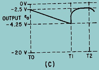
The waveforms for the circuit are shown in views (B) and (C). With no input signals, Q1 is biased near saturation by R1. The voltage across C1 is very low (-2.5 volts) because load resistor R3 drops most of the applied voltage. The transistor must be cut off to allow C1 to charge. To cut off Q1, a positive rectangular wave is used. Figure 3-47B. - Transistor sawtooth generator (pnp).
Figure 3-47C. - Transistor sawtooth generator (pnp).
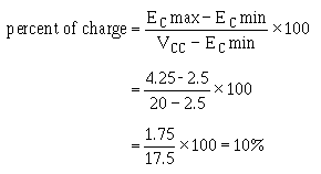
Since Q1 is a pnp transistor, a positive voltage must be used to drive it to cutoff. Figure 3-47, view (B), shows a rectangular wave input 500 microseconds long on the positive alternation. At T0, the positive gate applied to the base of Q1 cuts off Q1. This effectively removes the transistor from the circuit (opens the switch), and C1 charges through R3 toward 20 volts. Starting with a charge of -2.5 volts at T0, C1 charges (T0 to T1) for 500 microseconds to -4.25 volts at T1. Let's determine the percent of charge:
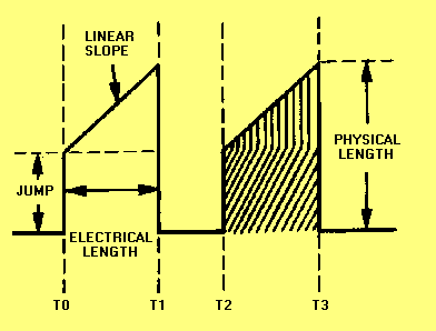
This allows nearly a linear rise of voltage across C1. Increasing the value of R3 or C1 increases the time constant. The capacitor will not charge to as high a voltage in the same period of time. Decreasing the width of the gate and maintaining the same time constant also prevents the capacitor from charging as much. With less charge on the capacitor, and the same voltage applied, linearity has been improved. Decreasing R3 or C1 or increasing gate width decreases linearity. Changing the applied voltage will change the charge on the capacitor. The percentage of charge remains constant; however, it does not affect linearity. At T1, the positive alternation of the input gate ends, and Q1 returns to a forward-bias condition. A transistor that is near saturation has very low resistance, so C1 discharges rapidly between T1 and T2, as shown in figure 3-47, view (C). The capacitor discharges in less than 200 microseconds, the length of the negative alternation of the gate. The negative gate is made longer than the discharge time of the capacitor to ensure that the circuit has returned to its original condition. From T1 to T2, the capacitor discharges and the circuit returns to its original condition, ready for another positive gate to arrive. The next positive gate arrives at T2 and the actions repeats. The amplitude of the output sawtooth wave is equal to 1.75 volts (4.25 volts minus 2.5 volts). The electrical length is the same as the positive alternation of the input gate, or 500 microseconds. The prt is 700 microseconds (500 + 200) and the prf is 1/prt or 1,428 hertz. Trapezoidal Sweep Generator Normally, oscilloscopes and synchroscopes use ELECTROSTATIC DEFLECTION and, as the name implies, electrostatic fields move the electron beam. The need here is for a sawtooth voltage waveform. Another method of electron beam deflection is ELECTROMAGNETIC DEFLECTION. Currents through a coil produce electromagnetic fields which position the beam of electrons. The electromagnetic system requires a sawtooth of current which increases at a linear rate. Because of the inherent characteristics of a coil, a sawtooth voltage does not cause a linear increase of current. A linear increase of current requires a TRAPEZOIDAL voltage waveform applied to a coil. This section discusses the generation of a trapezoidal wave. Figure 3-48 shows a trapezoidal wave. The wave consists of a sharp, almost instantaneous jump in voltage followed by a linear rise to some peak value. The initial change in voltage at T0 is called a JUMP or STEP. The jump is followed by a linear sawtooth voltage rise. The time from the jump to the peak amplitude is the sum of the jump voltage and the sawtooth peak; where the peak value occurs is the electrical length. The peak voltage amplitude is the sum of the jump voltage and the sawtooth peak voltage. The waveshape can be considered a combination of a rectangular wave and a sawtooth wave. Figure 3-48. - Trapezoidal waveform.
The inductance and resistance of a coil form a series RL circuit. The voltage drop across this inductance and resistance must be added to obtain the voltage waveform required to produce a linear rise in current. A linear rise of current produces a linear rise of voltage across the resistance of the coil and a constant voltage drop across the inductance of the coil. |
 
|