Custom Search
|
|
  |
|
|
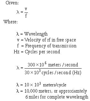
LENGTH OF A TRANSMISSION LINE A transmission line is considered to be electrically short when its physical length is short compared to a quarter-wavelength 1/4 l) of the energy it is to carry. NOTE: In this module, for ease of reading, the value of the wavelength will be spelled out in some cases, and in other cases, the numerical value will be used. A transmission line is electrically long when its physical length is long compared to a quarter-wavelength of the energy it is to carry. You must understand that the terms "short" and "long" are relative ones. For example, a line that has a physical length of 3 meters (approximately 10 feet) is considered quite short electrically if it transmits a radio frequency of 30 kilohertz. On the other hand, the same transmission line is considered electrically long if it transmits a frequency of 30,000 megahertz. To show the difference in physical and electrical lengths of the lines mentioned above, compute the wavelength of the two frequencies, taking the 30-kilohertz example first:
Now, computing the wavelength for the line carrying 30,000 megahertz:
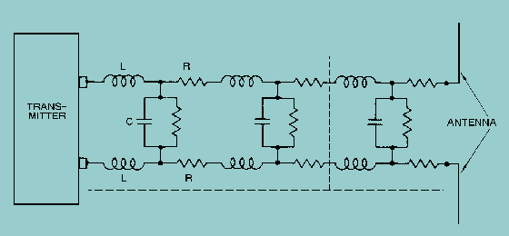
Thus, you can see that a 3-meter line is electrically very short for a frequency of 30 kilohertz. Also, the 3-meter line is electrically very long for a frequency of 30,000 megahertz. When power is applied to a very short transmission line, practically all of it reaches the load at the output end of the line. This very short transmission line is usually considered to have practically no electrical properties of its own, except for a small amount of resistance. However, the picture changes considerably when a long line is used. Since most transmission lines are electrically long (because of the distance from transmitter to antenna), the properties of such lines must be considered. Frequently, the voltage necessary to drive a current through a long line is considerably greater than the amount that can be accounted for by the impedance of the load in series with the resistance of the line. The electrical characteristics of a two-wire transmission line depend primarily on the construction of the line. The two-wire line acts like a long capacitor. The change of its capacitive reactance is noticeable as the frequency applied to it is changed. Since the long conductors have a magnetic field about them when electrical energy is being passed through them, they also exhibit the properties of inductance. The values of inductance and capacitance presented depend on the various physical factors that we discussed earlier. For example, the type of line used, the dielectric in the line, and the length of the line must be considered. The effects of the inductive and capacitive reactances of the line depend on the frequency applied. Since no dielectric is perfect, electrons manage to move from one conductor to the other through the dielectric. Each type of two-wire transmission line also has a conductance value. This conductance value represents the value of the current flow that may be expected through the insulation. If the line is uniform (all values equal at each unit length), then one small section of the line may represent several feet. This illustration of a two-wire transmission line will be used throughout the discussion of transmission lines; but, keep in mind that the principles presented apply to all transmission lines. We will explain the theories using LUMPED CONSTANTS and DISTRIBUTED CONSTANTS to further simplify these principles. A transmission line has the properties of inductance, capacitance, and resistance just as the more conventional circuits have. Usually, however, the constants in conventional circuits are lumped into a single device or component. For example, a coil of wire has the property of inductance. When a certain amount of inductance is needed in a circuit, a coil of the proper dimensions is inserted. The inductance of the circuit is lumped into the one component. Two metal plates separated by a small space, can be used to supply the required capacitance for a circuit. In such a case, most of the capacitance of the circuit is lumped into this one component. Similarly, a fixed resistor can be used to supply a certain value of circuit resistance as a lumped sum. Ideally, a transmission line would also have its constants of inductance, capacitance, and resistance lumped together, as shown in figure 3-9. Unfortunately, this is not the case. Transmission line constants are distributed, as described below. Figure 3-9. - Equivalent circuit of a two-wire transmission line.
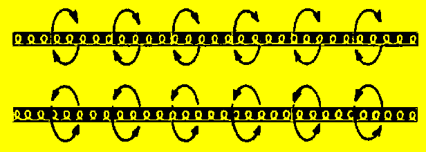
DISTRIBUTED CONSTANTS Transmission line constants, called distributed constants, are spread along the entire length of the transmission line and cannot be distinguished separately. The amount of inductance, capacitance, and resistance depends on the length of the line, the size of the conducting wires, the spacing between the wires, and the dielectric (air or insulating medium) between the wires. The following paragraphs will be useful to you as you study distributed constants on a transmission line. Inductance of a Transmission Line When current flows through a wire, magnetic lines of force are set up around the wire. As the current increases and decreases in amplitude, the field around the wire expands and collapses accordingly. The energy produced by the magnetic lines of force collapsing back into the wire tends to keep the current flowing in the same direction. This represents a certain amount of inductance, which is expressed in microhenrys per unit length. Figure 3-10 illustrates the inductance and magnetic fields of a transmission line. Figure 3-10. - Distributed inductance
Capacitance of a Transmission Line Capacitance also exists between the transmission line wires, as illustrated in figure 3-11. Notice that the two parallel wires act as plates of a capacitor and that the air between them acts as a dielectric. The capacitance between the wires is usually expressed in picofarads per unit length. This electric field between the wires is similar to the field that exists between the two plates of a capacitor. Figure 3-11. - Distributed capacitance.
Resistance of a Transmission Line The transmission line shown in figure 3-12 has electrical resistance along its length. This resistance is usually expressed in ohms per unit length and is shown as existing continuously from one end of the line to the other. Figure 3-12. - Distributed resistance.
Q.16 What must the physical length of a transmission line be if it will be operated at 15,000,000 Hz? Use the formula:
Q.17 What are two of the three physical factors that determine the values of
capacitance and inductance of a transmission line? |
|