|
REDRAWING CIRCUITS FOR CLARITY
You will notice that the schematic diagrams you have been working with have shown parallel circuits drawn as neat square figures, with each branch easily identified.
In actual practice the wired circuits and more complex schematics are rarely laid out in this simple form. For this reason, it is important for you to recognize that circuits can be drawn in a variety of ways, and to learn some of the techniques for redrawing them into their simplified form. When a circuit is redrawn for clarity or to its simplest form, the following steps are used.
Trace the current paths in the circuit.
Label the junctions in the circuit.
Recognize points which are at the same potential.
Visualize a rearrangement, "stretching" or "shrinking," of connecting wires.
Redraw the circuit into simpler form (through stages if necessary).
To redraw any circuit, start at the source, and trace the path of current flow through the circuit. At points where the current divides, called JUNCTIONS, parallel branches begin. These junctions are key points of reference in any circuit and should be labeled as you find them. The wires in circuit schematics are assumed to have NO RESISTANCE and there is NO VOLTAGE drop along any wire. This means that any unbroken wire is at the same voltage all along its length, until it is interrupted by a resistor, battery, or some other circuit component. In redrawing a circuit, a wire can be "stretched" or "shrunk" as much as you like without changing any electrical characteristic of the circuit.
Figure 3-56(A) is a schematic of a circuit that is not drawn in the box-like fashion used in previous illustrations. To redraw this circuit, start at the voltage source and trace the path for current to the junction marked (a). At this junction the current divides into three paths. If you were to stretch the wire to show the three current paths, the circuit would appear as shown in figure 3-56(B).
Figure 3-56. - Redrawing a simple parallel circuit.
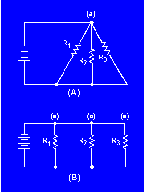
While these circuits may appear to be different, the two drawings actually represent the same circuit. The drawing in figure 3-56(B) is the familiar box-like structure and may be easier to work with. Figure 3-57(A) is a schematic of a circuit shown in a box-like structure, but may be misleading. This circuit in reality is a series-parallel circuit that may be redrawn as shown in figure 3-57(B). The drawing in part (B) of the figure is a simpler representation of the original circuit and could be reduced to just two resistors in parallel.
Figure 3-57. - Redrawing a simple series-parallel circuit.

|
|


