|
Redrawing a Complex Circuit
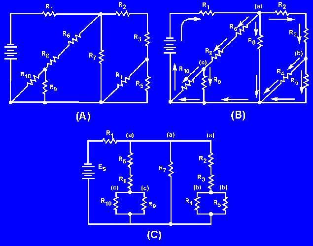
Figure 3-58(A) shows a complex circuit that may be redrawn for clarification in the following steps.
Figure 3-58. - Redrawing a complex circuit.

NOTE: As you redraw the circuit, draw it in simple box-like form. Each time you reach a junction, a new branch is created by stretching or shrinking the wires.
Start at the negative terminal of the voltage source. Current flows through R1 to a junction and divides into three paths; label this junction (a). Follow one of the paths of current through R2 and R3 to a junction where the current divides into two more paths. This junction is labeled (b).
The current through one branch of this junction goes through R5 and back to the source. (The most direct path.) Now that you have completed a path for current to the source, return to the last junction, (b). Follow current through the other branch from this junction. Current flows from junction (b) through R4 to the source. All the paths from junction (b) have been traced. Only one path from junction (a) has been completed. You must now return to junction (a) to complete the other two paths. From junction (a) the current flows through R7 back to the source. (There are no additional branches on this path.) Return to junction (a) to trace the third path from this junction. Current flows through R 6 and R8 and comes to a junction. Label this junction (c). From junction (c) one path for current is through R 9 to the source. The other path for current from junction (c) is through R10 to the source. All the junctions in this circuit have now been labeled. The circuit and the junction can be redrawn as shown in figure 3-58(C). It is much easier to recognize the series and parallel paths in the redrawn circuit.
What is the total resistance of the circuit shown in figure 3-59? (Hint: Redraw the circuit to simplify and then use equivalent resistances to compute for RT.)
Figure 3-59. - Simplification circuit problem.

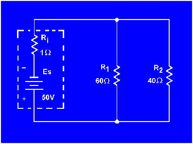
What is the total resistance of the circuit shown in figure 3-60?
Figure 3-60. - Source resistance in a parallel circuit.

What effect does the internal resistance have on the rest of the circuit shown in figure 3-60?
|


