
TM 11-6625-444-14-2
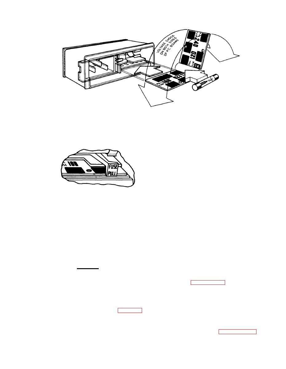
SELECTION OF OPERATING VOLTAGE
1 . Open cover door and rotate fuse-pull to left.
Operating voltage is shown in module window. 2 . Select operating voltage by orienting PC board
to position the desired voltage on top-left side
then push board firmly into module slot.
3 . Rotate fuse-pull back into normal position and
then re-insert fuse in holders, using caution to
select correct fuse value.
EL6UZ005
(2) Connect the line power cord to the in-
put power receptacle on the rear panel and then
plug it into a convenient line power receptacle.
for installation in a standard 19-inch wide equip-
ment rack by use of the rack adapter kit.
b. Procedure
CAUTION
Insure that the round pin on the line
er as detailed in paragraph 6-9. b.
power cord is always connected to
an "earth" ground.
(2) Remove the two rear feet from the dust
cover.
(3) Make the appropriate connections to
(3) Remove the two front feet and tilt bail
the front and rear panels as shown in figure 2-3.
stand from the dust cover.
The voltage input can be applied to either the
front or rear panel terminals. Selection of the
(4) Re-assemble the bottom dust cover to
terminals is accomplished by a front panel push-
the voltmeter as detailed in paragraph 6-12. g.,
button switch.

