Custom Search
|
|
 
|
||
|
TESTING SOLID-STATE DEVICES After electrical generating plants, distribution systems, communications systems, and other
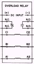
Figure 4-18.\Solid-state overload protective relay. electrical apparatus and equipment have been constructed and put into operation, they must be tested, inspected, and maintained. To do this, you must know how to operate the various testing and measuring instruments to test for grounds, opens, and shorts and be able to measure current, voltage, power, resistance, frequency, and so forth, The theory of operation for basic types of testing and measuring devices, such as megohmmeters, voltmeters, ammeters, and ohmmeters, is explained in the Construction Electrician 3 & 2 training manual. More sophisticated types of test equipment presently being distributed to the battalions and shore facilities will be discussed in this chapter. These include the transistor tester, waveform analyzer (oscilloscope), and the capacitor-inductor analyzer. You undoubtedly recognize the importance of becoming familiar with any test equipment capable of performing tests on these newer components and the advantages each of these specialized instruments has. Knowledge on the use of these instruments will enable you to place equipment into operation status quickly and safely. As you increase your capabilities, you should find it easier to advance in rate. Solid-state devices, although generally more rugged mechanically than vacuum tubes, are susceptible to damage by excessive heat and electrical overload. The following precautions have to be taken in servicing transistorized equipment: Check equipment and soldering irons to make certain that there is no leakage current from the power source. If leakage current is detected, use isolation transformers. Do not use ohmmeter ranges that require a current of more than 1 milliampere in the test circuit for testing transistors. Do not use battery eliminators to furnish power for transistor test equipment because these devices have poor voltage regulation and possibly high ripple voltage. When soldered connections are required, keep the heat applied to a transistor to a minimum by using a low-wattage soldering iron and heat shunts, such as long-nose pliers, on the transistor leads. Check all associated circuits for defects before rejecting a transistor. Remove all power from the equipment before you replace a transistor or other circuit part. On equipment with closely spaced parts, the placement of conventional test probes is often the cause of accidental short circuits between adjacent terminals. Momentary short circuits, which rarely cause damage to a vacuum tube, may ruin a transistor. To avoid accidental shorts, you can cover test probes with insulation for all but a short length of the tip.
RECTIFIER DIODE TESTING A convenient test for a rectifier diode requires only an ohmmeter. The forward-and-back resistance can be measured at a voltage determined by the battery potential of the ohmmeter and the resistance range at which the meter is set. When the test leads of the ohmmeter are connected to the diode, a resistance will be measured that is different from the resistance indicated if the leads are reversed. The smaller value is called the FORWARD resistance, and the larger value is called the BACK resistance. If the ratio of back-to-forward resistance is greater than 10:1, the diode should be capable of functioning as a rectifier. This is a limited test and does not take into account the action of the diode at voltages of different magnitudes and frequencies. Another test that may be performed on a diode is the front-to-back current leakage. This test will be discussed in the "Transistor Testing" portion of this chapter.
|
||
|
||