Custom Search
|
|
 
|
||
|
Underfrequency Protective Relay The underfrequency relay (fig. 4-16) is a solidstate device that functions to protect the load in the event generator frequency decreases below preset limits. It actuates when the frequency decreases to 55 hertz for 60-hertz operation and 46 hertz for 50-hertz operation. Upon actuation, contacts within the relay close to signal the annunicator and open to de-energize the generator breaker (contactor), resulting in a display of the fault condition and removal of the load from the generator. Frequency sensing is accomplished by a tuned circuit consisting of capacitors C1 and C2 and components in the encapsulated base. Zener diodes CR1, CR2, and CR3 limit the peak voltage to the tuned circuit. The ac output of the tuned circuit is rectified by diode CR4 and applied to a voltage divider consisting of resistors R1, R2, R3, and R4. Transistor Q1 compares the voltage at the wiper of potentiometer R3 with the reference voltage established by zener diode CR7. When transistor Q1 conducts, transistor 42 operates as a switch to control the coil voltage on a relay contained in the encapsulated base. Both transistors Q1 and Q2 and the relay in the encapsulated base are energized when the frequency of the input voltage to terminals 1 and 2 is normal frequency (50 to 60 hertz). When an underfrequency condition occurs, the voltage at the base of transistor Q1 is not sufficient for conduction. This causes the relay to be de-energized and its contacts to switch. The underfrequency trip point is adjusted by potentiometer R3.
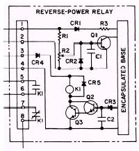
Reverse-Power Protective Relay The reverse-power relay (fig. 4-17) is a solid-state device that functions to protect the generator in the event of a reverse-power operating condition during parallel operation. It operates in conjunction with the load measurement unit. This unit produces a dc output voltage whose polarity and magnitude are functions of
Figure 4-16.\Solid-state underfrequency protective relay.,
Figure 4-17.\Solid-state reverse-power protective relay. the total load on the generator set regardless of phase or power factor. When the reverse-power flow into the generator exceeds 20 percent of rated load, the load measurement unit output has sufficient magnitude and correct polarity to cause the reverse-power relay to activate. Upon actuation, contacts within the reverse-power relay close to signal the annunicator and open to de-energize the generator breaker (contactor). This results in a display of the fault condition and removal of the load from the generator. 1. During normal operation with power passing from the generator set to the load, the load measurement unit impresses a dc signal across terminals 1 and 2 of the reverse-power relay, with terminal 1 negative and terminal 2 positive. This reverse-biases transistor Q1 off, causing Q2 and Q3 to be off and relay coil K1 to be de-energized. Thus, under all conditions of forward power by the generator set, relay K1 is de-energized, terminals 5 and 6 remain open, and terminals 7 and 8 are shorted. 2. Reverse-power trip-level-control potentiomenter R2 is factory adjusted to cause relay coil K1 to be energized when dc voltage of 2 volts is impressed across terminals 1 and 2, with terminal 1 positive and terminal 2 negative. 3. When the system reverse power reaches 20 percent, the dc voltage across the wiper of R2 and terminal 2 has sufficient magnitude to turn Q1 on. The superimposed ac voltage on the dc input to terminals 1 and 2 is then impressed across the anode of CR2 and terminal 4. Diode CR3 rectifies this ac signal and capacitor C2 smooths it. The resultant dc voltage forward-biases Q2 and Q3 on, causing relay coil K1 to become energized. Overload Protective Relay The overload (overcurrent) relay (fig. 4-18) is a solid-state device whose function is to protect the load in the event of an overload condition. An "overload condition" is defined as the state in which generator output current in any phase exceeds 110 percent of rated value. The overload relay is a current-sensing device and operates on an inverse-time principle as the current in any phase (coil A, B, or C) exceeds the overload state. At the point just above 130 percent of rated current, the overload relay will actuate in approximately 10 minutes. Upon actuation, contacts within the overload relay close to signal the annunicator and open to de-energize the generator breaker (contactor). This results in the display of the fault condition and the removal of the load from the generator. |
 |
|
|
||