Custom Search
|
|
 
|
||
|
SOLID-STATE PROTECTIVE RELAYS A protective relay is a device that when energized by suitable inputs responds to these inputs in a prescribed manner to indicate or isolate an abnormal operating condition. The inputs to these protective devices are usually electrical but may be mechanical, thermal, or a combination of these quantities. This discussion will be concerned with solid-state relays having electrical inputs. Overvoltage Protective Relay The overvoltage relay (fig. 4-14) is a solid-state device that functions to protect the load in the event that generator voltage exceeds preset limits. It actuates after a predetermined time delay when the generator voltage rises to approximately 125 percent of the rated output voltage. Upon actuation, contacts within the overvoltage relay close (K1, 7-8) to display the fault condition at the annunciator and open (K1, 3-4) to secure the generator set. 1. The ac input voltage (terminals 1 and 2) is rectified by diode CR1 and applied to a voltage divider network consisting of resistors R2, R3, and R5. Zener diode CR4 conducts when the voltage at the wiper of R5 exceeds its zener breakdown voltage. The point at which the ac input voltage causes the zener breakdown of CR2 can be adjusted by R5. 2. When an overvoltage condition occurs, zener diode CR4 conducts and triggers SCR1 for conduction. This energizes relay K1 and causes
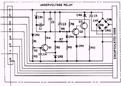
Figure 4-14.\Solid-state overvoltage protective relay. its contacts to transfer. Resistor R1 limits the current to the relay while the voltage to the relay is limited to a peak value of 30 volts by zener diodes CR2 and CR3. 3. Resistor R4 and capacitor C3 prevent transients from triggering silicon controlled switch SCR1 into conduction. Undervoltage Protective Relay The undervoltage relay (fig. 4-15) functions to protect the load in the event the generator decreases below preset limits. It actuates after a predetermined time delay when generator voltage decreases to approximately 75 percent of the rated output voltage. Upon actuation, contacts within the undervoltage relay close to signal the annunicator and open to de-energize the generator breaker (contactor), resulting in a display of the fault condition and removal of the load from the generator. 1. The single-phase input voltage is rectified by diode CR2 and applied to a sampling network consisting of resistors R1, R2, and R3. The dc voltage sampled at the wiper of potentiometer R2 is filtered by capacitor C4. Transistor Q1 compares the sample voltage on capacitor C4 to a reference voltage obtained by zener diode CR3. 2. When the input voltage is above the trip point, transistor Q1 conducts. This causes zener diode CR1 to limit the voltage across capacitors C1, C2, and C3 to 15 volts. This voltage forwardbiases transistors 42 and 43 for conduction. Transistors 42 and 43 function as a switch to energize a relay contained in the encapsulated base.
Figure 4-15.\Solid-state undervoltage protective relay.
3. When the input voltage is below the trip point or approximately the zener breakdown voltage of CR3, transistor Q1 will turn off. When this happens, the capacitors discharge through resistors R6 and R8 and zener diode CR6. When the voltage across these capacitors falls below the zener breakdown voltage of CR6, transistors Q2 and Q3 will turn off. This de-energizes the relay. 4. Diodes CR7 through CR10 are used as a full-wave bridge to rectify the input voltage to a dc level for the detector circuit and the relay. Capacitor C5 reduces the ripple of the rectified voltage to prevent relay chatter. |
 
|
|
|
||