Custom Search
|
|
 
|
||
|
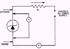
ZENER DIODE TESTING The testing of zener diodes requires a variable dc power supply. A typical test circuit can be constructed, as shown in figure 4-19. In this circuit, the variable power supply is used to adjust the input voltage to a suitable value for the zener diode being tested. Resistor R1 limits the current through the diode. With the zener diode connected as shown in figure 4-19, no current will flow until the voltage across the diode is equal to the zener voltage. If the diode is connected in the opposite direction, current will flow at a low voltage, usually less than 1 volt. Current flow at a low voltage in both directions indicates that the zener diode is defective.
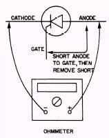
Figure 4-19.\Testing a zener diode. SILICON CONTROLLED RECTIFIER TESTING To test an SCR, connect an ohmmeter between the anode and cathode, as shown in figure 4-20. Start the test at R 10,000 and reduce the value gradually. The SCR under test should show a high resistance regardless of the ohmmeter polarity. The anode, which is connected to the positive lead to the ohmmeter, is now to be shorted to the gate. This will cause the SCR to conduct, giving a low resistance reading on the ohmmeter. Removing the anode-to-gate short will not stop the SCR from conducting. Removal of either of the ohmmeter leads will cause the SCR to stop conducting, and the resistance reading will then
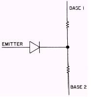
Figure 4-20.\Testing an SCR with an ohmmeter. return to its previous high value. Some SCRs will not operate when connected to an ohmmeter. The reason for this is that the ohmmeter does not supply enough current. However, most of the SCRs in Navy equipment can be tested by the ohmmeter method. If an SCR is sensitive, the R 1 scale may supply too much current to the device and damage it. It is advisable to try testing sensitive SCRs on the higher resistance scales. An SCR can also be tested for switching action and leakage, as discussed in the "Transistor Testing" section of this chapter. UNIJUNCTION TRANSISTOR TESTING Testing a unijunction transistor (UJT) is a relatively easy task if you view the UJT as being a diode connected to the junction of two resistors, as shown in figure 4-21. With an ohmmeter, measure the resistance between base 1 and base 2; then reverse the ohmmeter leads and take another reading. Both readings should show the same high resistance regardless of the meter lead polarity. Connect the ohmmeter's negative lead to the UJT's emitter. Using the positive lead, measure the resistance from the emitter to base 1, and then from the emitter to base 2. Both readings should indicate high resistances approximately equal to each other. Disconnect the negative lead from the emitter and connect the positive lead to it. Using the negative lead, measure the resistance from the emitter to base 1, then from emitter to base 2. Both readings
Figure 4-21.\Unijunction transistor equivalent circuit.
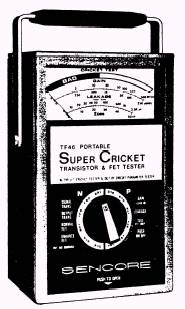
should indicate low resistances approximately equal to each other. Most transistors that fail do so completely. These transistors can be detected by using the transistor gain test. Two exceptions are transistors that are just starting to fail and transistors in critical bias circuits. The quality of these transistors can be checked by using the transistor leakage test. An accurate, easy-to-use transistor tester (fig. 4-22) that allows both in- and out-ofcircuit testing can make you more efficient in troubleshooting solid-state circuits. The transistor tester can also test diodes, SCRs, and field effect transistors (FETs). An FET is a device that combines the high input impedance of the vacuum tube with all the advantages of the transistor. For detailed testing information on FETs, consult the transistor tester operator's manual.
Figure 4-22.\Sencore TF46 transistor and FET tester.
Transistor Gain The transistor gain test provides a safe and reliable method of determining if a transistor has gain. The gain test is a Go/No-Go test providing a test tone and meter indication that indicates gain is present. No technical information is needed for testing for transistor gain. The same procedure is used for testing a transistor in or out of circuit. WARNING Be sure power to the transistor has been removed and filter capacitors discharged before connecting the test leads. To test for transistor gain: 1. Connect the three test leads to the three leads of the transistor in any order. NOTE: The position (up or depressed) of the PARAMETER SELECTOR buttons (to the left of the PERMUTATOR SWITCH) has no effect on the test. 2. Rotate the PERMUTATOR SWITCH one complete turn while watching the meter and/or listening for the test tone. If the transistorhas gain, the meter will read in the GOOD portion of the GAIN scale in either one or two PERMUTATOR SWITCH positions. 3. If the transistor tests BAD in circuit, check the schematic of the transistor being tested to see if there is a low-impedance shunt path around the transistor (between any two elements). It is recommended that transistors that check BAD in circuit be removed from the circuit and tested again to eliminate the possibility of external' loading. If the transistor now checks GOOD, perform the out-of-circuit leakage check. If a transistor checks BAD in circuit and GOOD out of circuit (including leakage), there is probably something wrong in the circuit.
|
||
|
||