Custom Search
|
|
 
|
||
|
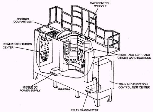
Launcher Hydraulic Systems There are three hydraulic systems associated with the launcher. They provide all the necessary hydraulic forces required to train, elevate, depress, and operate the guide arm components. The train power drive system is located under the launcher platform. It drives the launcher through the training circle gear mounted to the base ring. The elevation power drive system is located inside the carriage. It drives the guide arms through the elevation arc mounted to the trunnion tube. In addition to elevating or depressing the guide arms, the elevation power drive system provides the main accumulator pressure for the guide arm components. Figure 7-27 shows the location of the elevation power drive and the guide arm accumulator and control assembly. The third hydraulic system is the launcher exercise and emergency accumulator system. (It is very similar to the exercise and emergency accumulator systems described with the RSR/hoist power drives.) This system is hydraulically connected to the elevation power drive system. Hydraulic fluid at reduced pressure is supplied to operate the guide arm components and the elevation power drive. LAUNCHING SYSTEM CONTROL The launching system control components perform three main functions: (1) They distribute electrical power, (2) they process system orders and responses, and (3) they perform tests to determine system readiness. As you study the Mk 26 GMLS control system, you will notice a break with tradition. Panels are no longer designated EP1, EP2, and so on, but are known by their full name or first-letter abbreviations. Most communications and interface between weapons control, FCS, and the GMLS are in digital word format. (There may be some terms presented here with which you are not yet familiar, but they will be explained later in the text.) Although not physically located in the GMLS area, the digital serial transceiver (DST) (shown in fig. 7-18) is a solid-state electronic module in the weapons control area. It serves as a communication Iink between WC and launching system control. This module receives parallel order data (electrical signals) from a computer in WC. It changes the order data from parallel to serial form for transmission to the ICS through cables. One cable connects to the digital interface module (DIM) and the other to the local control module. The order data signals direct launching system operations in remote control. The DST also provides response data from launching system control to WC. The DST receives serial response data from the local control module on cables. It changes these data from serial to parallel form. In parallel form, these data are in the correct format for transmission to the WC computer. The response data show the status of the launching system. Integrated Control Station (ICS) The integrated control station (ICS) (fig. 7-30), located at the hoist end of the magazine, is a water- and blast-tight compartment. It houses most of the power, control, monitoring, and test equipments of the system. The major cabinets in the ICS are the power distribution center (PDC), the MCC, the right- and left-hand circuit card housings, and the train and elevation control test center.
Figure 7-30.-Integrated control station. POWER DISTRIBUTION CENTER (PDC).- PDC houses the electrical components that distribute and regulate all power to the launching system. It is comparable to other EP1 power panels. |
 |
|
|
||