Custom Search
|
|
 
|
||
|
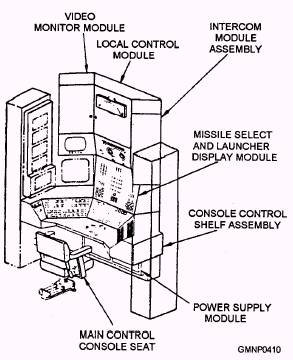
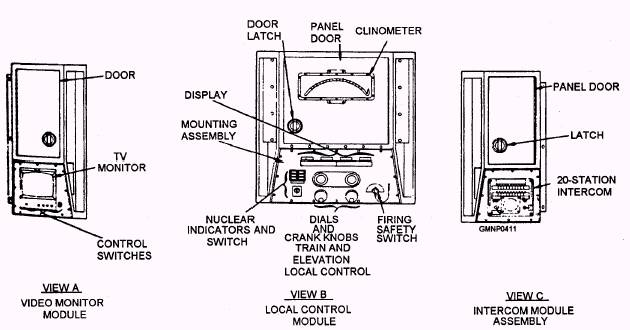
MAIN CONTROL CONSOLE (MCC).- The MCC (fig. 7-31) is a modular, wraparound type of unit. It contains the operating controls and indicators needed for programming and monitoring launching system operations. The individual modules in the MCC are shown in separate figures for clarity. The video monitor module (fig. 7-32, view A) consists of electrical components and a TV screen used for watching either the launcher area or rear magazine areas. The local control module (fig. 7-32, view B) is used by the MCC operator as the local control station for the train and elevation power drives. Also provided are a firing safety switch, rail and system nuclear lock indications, and digital readout displays of both launcher ordered and actual positions. This module acts as a communication link between the DST and other ICS equipments. The intercom module assembly (fig. 7-32, view C) has a 20-station intercom to other parts of the ship. A small compartment can store a set of sound-powered phones for the MCC operator (plus a deck of cards,
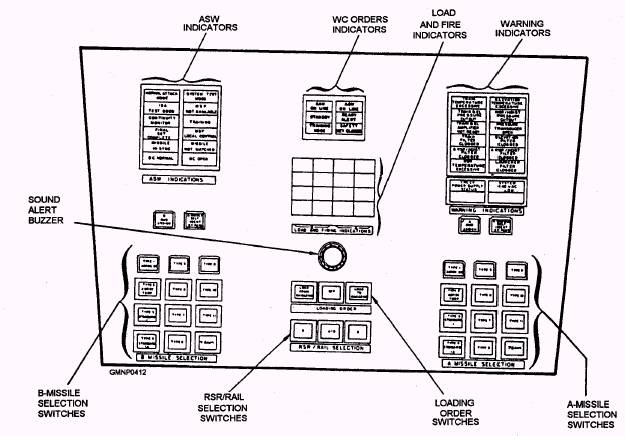
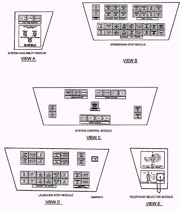
Figure 7-31.-Main control console. favorite magazines, and the latest copy of the GM training manual). The missile select and launcher display module (fig. 7-33) has a variety of switches and indicators used by the MCC operator during remote and local control modes. When the system is operating in remote control, the operator monitors the indicators that show the status of power drives, remote WC orders, and load-and-fire operations. When the launching system is operating in local control, the operator selects the type of missile, a load (or unload) operation, and either one or both launcher guide arms and RSR/hoist equipment. The console control shelf assembly is directly in front of the MCC operator's chair. It provides a horizontal working space and mounts five separate modules. They will be described left to right. The system availability module (fig. 7-34, view A) contains push-button indicating and toggle switches. They are used to tell WC of launching system availability status and to select various test modes. The strikedown step module (fig. 7-34, view B) contains the strikedown hatch, emergency motor, main motor, and strikedown step control push-button indicating switches. The system control module (fig. 7-34, view C) contains the all motors start/stop, loading selection, pointing selection, magazine safety, launcher warning bell, and system selection groups of switches. The launcher step module (fig. 7-34, view D) contains the launcher step control, jettison, and launcher emergency drive groups of switches. This module provides the controls and indicators for performing and monitoring load and jettison operations and for directing the launcher using the emergency motors. The telephone selector module (fig. 7-34, view E) has two rotary switches and a telephone jack. The load and firing indications lamp test switch is a 13-position rotary switch. The MCC operator uses this switch to test the load-and-fire indicator lamps in the missile select and launcher display module. The telephone selector switch is a six-position rotary switch. The MCC operator positions this switch to select telephone channels to communicate with either WC or local launching system sound-powered phones.
Figure 7-32.-Main control console modules.
Figure 7-33.-Missile select and launcher display module.
Figure 7-34.-Console control shelf assembly modules. The last component of the MCC is the power supply module (fig. 7-35). Electrical receptacles on the bottom of the module connect it to the PDC. The components of the module provide regulated dc power to solenoids and solid-state circuits throughout the system. Many of the various rated de-power supplies are identical, interchangeable, and adjustable. RIGHT- AND LEFT-HAND CIRCUIT CARD HOUSINGS.- The right- and left-hand circuit card housings (fig. 7-36) are on either side of the MCC. These housings contain the electrical/electronic components used for system control. The two housings are arranged the same but show different information. The right-hand circuit card housing shows A-side, train, and elevation system status. The left-hand circuit card housing shows B-side and strikedown system status. |
 |
|
|
||