Custom Search
|
|
 
|
||
|
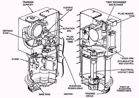
Blast Door and Span Rail A blast door is mounted to the platform under each guide arm. (See fig. 7-17.) In opening, the door unlatches, raises, and swings aside. This provides sufficient clearance for a missile with fins extended to pass through. In closing, the sequence is reversed and a seal on the bottom of the door forms a water- and blast-tight closure, A separate span rail assembly (not part of the blast door) is located inside the door opening. (See fig. 7-22.) It is a pivoting rail segment, about 3 feet long, extended by a hydraulic piston. A bumper pad on the rail contacts the edge of the blast door opening to provide a positive aligning stop. When fully extended, aligning and latch rods lock the span rail to the freed rail of the guide arm and the fixed rail of the magazine. Guide Arm The guide arm structure (fig. 7-28) is a steel weldment with three different guide rails, ASW-related components, and AAW-related components.
Figure 7-27.-Carriage, general arrangement.
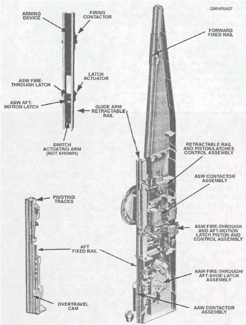
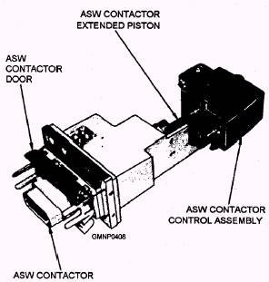
Figure 7-28.-Guide components, general arrangement. Depending on the mode (AAW or ASW) in which the is about 50 inches. It contains a pair of hinged rail system is operating, the applicable equipments track segments and an overtravel cam. The pivoting connect to and prepare the missile for flight. segments, about 19 inches long, open and close to form the rail track for the aft shoe of an AAW missile. GUIDE RAILS.- Of the three individual guide The overtravel cam accommodates a positioning link rail sections on each guide arm, two are fixed and on the hoist chain and pawl to allow proper one is movable. The total length of the aft fixed rail positioning of a missile on the guide rail. The forward fixed rail is about 11 1/2 feet long and contains no fictional components. This rail is used only when firing ASW missiles and provides the longer on-rail guidance required by this type of missile. The retractable rail is mounted between the two fixed rails and is about 6 1/2 feet long. During a loading operation, it extends to align with the aft freed rail. This combination forms one continuous rail track for AAW and ASW forward missile shoes. With an AAW missile, the rail remains extended until the round is launched. As the missile moves forward, the rail retracts to clear the fins of the missile. With an ASW missile, the rail retracts as soon as the round is loaded onto the guide arm. It remains retracted to form the longer guidance track with the forward freed rail. ASW RAIL COMPONENTS.- There are three different components involved with preparing and launching ASW missiles on the guide arm. The ASW fire-thru and aft-motion latch piston and control assembly operates two of these devices. The ASW fire-thru latch is extended through the rail to engage the forward edge of the aft missile shoe. As it extends, it causes the ASW aft shoe restraining latch (on the pusher bar) to release. During firing, the fire-thru latch holds the ASW missile on the rail until about 2,600 pounds of thrust is developed by the rocket motor and then it trips (releases). The ASW aft-motion latch is extended by the same assembly to engage the rear edge of the aft missile shoe. It secures the missile to the rail and allows the pusher bar and hoist chain to retract to the magazine. The third component is the ASW contactor assembly (fig. 7-29). When it extends, the contactor pins penetrate a pad near the aft shoe of the missile. Electrical power, preflight data, and firing voltages are transmitted through this connection from UBFCS and WCS to circuits within the missile. At firing, the contactor retracts into the guide arm. AAW RAIL COMPONENTS.- The rail components required to load, prepare, and launch AAW missiles involve three separate (and more complicated) assemblies. Located above the aft fixed rail, the AAW fire-thru and aft-motion latch assembly (see fig. 7-28) is functionally similar to its ASW counterpart. The AAW fire-thru latch trips from 4,000 to 4,600 pounds. The AAW aft-motion latch extends to release the AAW aft-shoe restraining latch (on the pusher bar) to secure the missile to the rail.
Figure 7-29.-ASW contactor assembly. The two hinged-rail segments (mentioned earlier on the aft fixed rail) operate with the aft-motion latch linkage. When an AAW missile is loaded to the rail, the segments are open to accept the missile. As the aft-motion latch extends, mechanical linkages cause the segments to pivot closed, engaging the aft missile shoe. In this position, the segments prevent any lateral movement of the missile. They also provide a short on-rail guidance track. After firing or during unloading, whenever the aft-motion latch retracts, the segments pivot open to release the shoes. A blast shield also operates with the aft-motion latch linkage. The shield extends with the latch. In this position, it can protect the mechanism from launch sequence, rocket firing voltage is applied, and the motor ignites. |
 |
|
|
||