Custom Search
|
|
  |
|
|
Effect of Frequency on Inductive Reactance In an a.c. circuit, an inductor produces inductive reactance which causes the current to lag the voltage by 90 degrees. Because the inductor "reacts" to a changing current, it is known as a reactive component. The opposition that an inductor presents to a.c. is called inductive reactance (XL). This opposition is caused by the inductor "reacting" to the changing current of the a.c. source. Both the inductance and the frequency determine the magnitude of this reactance. This relationship is stated by the formula:
As shown in the equation, any increase in frequency, or "f," will cause a corresponding increase of inductive reactance, or "XL." Therefore, the INDUCTIVE REACTANCE VARIES DIRECTLY WITH THE FREQUENCY. As you can see, the higher the frequency, the greater the inductive reactance; the lower the frequency, the less the inductive reactance for a given inductor. This relationship is illustrated in figure 1-2. Increasing values of XL are plotted in terms of increasing frequency. Starting at the lower left corner with zero frequency, the inductive reactance is zero. As the frequency is increased (reading to the right), the inductive reactance is shown to increase in direct proportion. Figure 1-2. - Effect of frequency on inductive reactance.
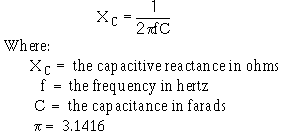
Effect of Frequency on Capacitive Reactance In an a.c. circuit, a capacitor produces a reactance which causes the current to lead the voltage by 90 degrees. Because the capacitor "reacts" to a changing voltage, it is known as a reactive component. The opposition a capacitor presents to a.c. is called capacitive reactance (XC). The opposition is caused by the capacitor "reacting" to the changing voltage of the a.c. source. The formula for capacitive reactance is:
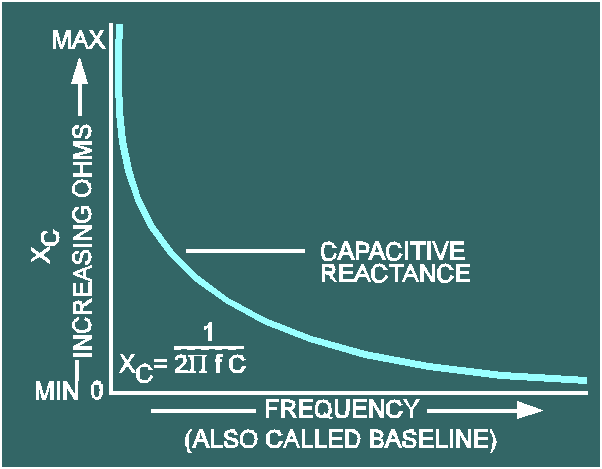
In contrast to the inductive reactance, this equation indicates that the CAPACITIVE REACTANCE VARIES INVERSELY WITH THE FREQUENCY. When f = 0, XC is infinite and decreases as frequency increases. That is, the lower the frequency, the greater the capacitive reactance; the higher the frequency, the less the reactance for a given capacitor. As shown in figure 1-3, the effect of capacitance is opposite to that of inductance. Remember, capacitance causes the current to lead the voltage by 90 degrees, while inductance causes the current to lag the voltage by 90 degrees. Figure 1-3. - Effect of frequency on capacitive reactance.
Effect of Frequency on Resistance In the expression for inductive reactance, XL = 2pfL, and in the expression for capacitive reactance,
both contain "f" (frequency). Any change of frequency changes the reactance of the circuit components as already explained. So far, nothing has been said about the effect of frequency on resistance. In an Ohm's law relationship, such as R = E/I no "f" is involved. Thus, for all practical purposes, a change of frequency does not affect the resistance of the circuit. If a 60-hertz a.c. voltage causes 20 milliamperes of current in a resistive circuit, then the same voltage at 2000 hertz, for example, would still cause 20 milliamperes to flow. NOTE: Remember that the total opposition to a.c. is called impedance (Z). Impedance is the combination of inductive reactance (XL), capacitive reactance (XC), and resistance (R). When dealing with a.c. circuits, the impedance is the factor with which you will ultimately be concerned. But, as you have just been shown, the resistance (R) is not affected by frequency. Therefore, the remainder of the discussion of a.c. circuits will only be concerned with the reactance of inductors and capacitors and will ignore resistance. A.c. Circuits Containing Both Inductive and Capacitive Reactances A.c. circuits that contain both an inductor and a capacitor have interesting characteristics because of the opposing effects of L and C. XL and XC may be treated as reactors which are 180 degrees out of phase. As shown in figure 1-2, the vector for XL should be plotted above the baseline; vector for XC, figure 1-3, should be plotted below the baseline. In a series circuit, the effective reactance, or what is termed the RESULTANT REACTANCE, is the difference between the individual reactances. As an equation, the resultant reactance is: X = XL - XC Suppose an a.c. circuit contains an XL of 300 ohms and an XC of 250 ohms. The resultant reactance is: X = XL - XC = 300 - 250 = 50 ohms (inductive) In some cases, the XC may be larger than the X L. If XL = 1200 ohms and XC = 4000 ohms, the difference is: X = XL - XC = 1200 - 4000 = -2800 ohms (capacitive). The total carries the sign (+ or -) of the greater number (factor). Q.1 What is the relationship between frequency and the values of (a) XL, (b)
XC, and (c) R? |
 |