Custom Search
|
|
  |
|
|
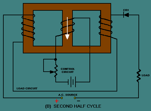
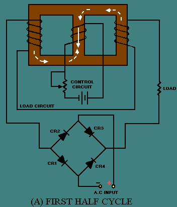
SIMPLIFIED MAGNETIC AMPLIFIER CIRCUITRY If the saturable-core reactor works, why do we need to add a rectifier to produce a magnetic amplifier? To answer this question, recall that in NEETS, module 2 - Introduction to Alternating Current and Transformers, you were told about hysteresis loss. Hysteresis loss occurs because the a.c. applied to a coil causes the tiny molecular magnets (or electron-spin directions) to realign as the polarity of the a.c. changes. This realignment uses up power. The power that is used for realignment is a loss as far as the rest of the circuit is concerned. Because of this hysteresis loss in the saturable-core reactor, the power gain is relatively low. A rectifier added to the load circuit will eliminate the hysteresis loss and increase the gain. This is because the rectifier allows current to flow in only one direction through the load coils. A simple half-wave magnetic amplifier is shown in figure 3-38. This is a half-wave magnetic amplifier because it uses a half-wave rectifier. During the first half cycle of the load voltage, the diode conducts and the load windings develop load flux as shown in view (A) by the dashed-line arrows. The load flux from the two load coils cancels and has no effect on the control flux. During the second half cycle, the diode does not conduct and the load coils develop no flux, as shown in view (B). The load flux never has to reverse direction as it did in the saturable-core reactor, so the hysteresis loss is eliminated. Figure 3-38A. - Simple half-wave magnetic amplifier. FIRST HALF CYCLE
Figure 3-38B. - Simple half-wave magnetic amplifier. SECOND HALF CYCLE
The circuit shown in figure 3-38 is only able to use half of the load voltage (and therefore half the possible load power) since the diode blocks current during half the load-voltage cycle. A full-wave rectifier used in place of CR1 would allow current flow during the entire cycle of load voltage while still preventing hysteresis loss. Figure 3-39 shows a simple full-wave magnetic amplifier. The bridge circuit of CR1, CR2, CR3, CR4 allows current to flow in the load circuit during the entire load voltage cycle, but the load current is always in the same direction. This current flow in one direction prevents hysteresis loss. View (A) shows that during the first half cycle of load voltage, current flows through CR1, the load coils, and CR3. View (B) shows that during the second half cycle, load current flows through CR2, the load coils, and CR4. Figure 3-39A. - Simple full-wave magnetic amplifier. FIRST HALF CYCLE
Figure 3-39B. - Simple full-wave magnetic amplifier. SECOND HALF CYCLE
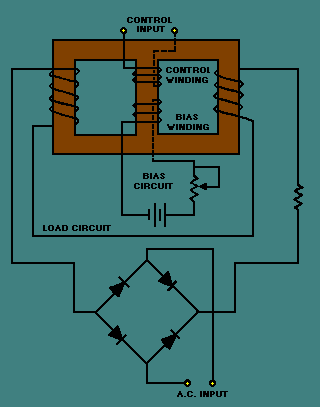
Up to this point, the control circuit of the magnetic amplifier has been shown with d.c. applied to it. Magnetic-amplifier control circuits should accept a.c. input signals as well as d.c. input signals. As shown earlier in figure 3-34, a saturable-core reactor has an ideal operating point. Some d.c. must always be applied to bring the saturable core to that operating point. This d.c. is called BIAS. the most effective way to apply bias to the saturable core and also allow a.c. input signals to control the magnetic amplifier is to use a bias winding. A full-wave magnetic amplifier with a bias winding is shown in figure 3-40. Figure 3-40. - Full-wave magnetic amplifier with bias winding.
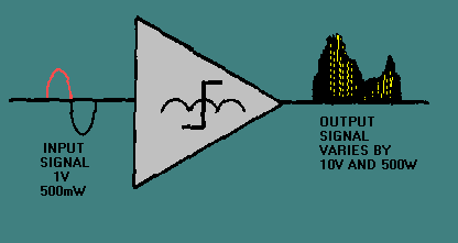
In the circuit shown in figure 3-40, the bias circuit is adjusted to set the saturable-core reactor at the ideal operating point. Input signals, represented by the a.c. source symbol, are applied to the control input. The true power of the load circuit is controlled by the control input signal (a.c.) The block diagram symbol for a magnetic amplifier is shown in figure 3-41. The triangle is the general symbol for an amplifier. The saturable-core reactor symbol in the center of the triangle identifies the amplifier as a magnetic amplifier. Notice the input and output signals shown. The input signal is a small-amplitude, low-power a.c. signal. The output signal is a pulsating d.c. with an amplitude that varies. This variation is controlled by the input signal and represents a power gain of 1000. Figure 3-41. - Magnetic amplifier input and output signals.
Some magnetic amplifiers are designed so a.c. goes through the load rather than pulsating d.c. This is done by placing the load in a different circuit position with respect to the rectifier. The principle of the magnetic amplifier remains the same: Control current still controls load current. Magnetic amplifiers provide a way of accurately controlling large amounts of power. They are used in servosystems (which are covered later in this training series), temperature or pressure indicators, and power supplies. This chapter has presented only the basic operating theory of saturable-core reactors and magnetic amplifiers. For your convenience, simple schematic diagrams have been used to illustrate this material. When magnetic amplifiers and saturable-core reactors are used in actual equipment, the schematics may be more complex than those you have seen here. Also, you may find coils used in addition to those presented in this chapter. The technical manual for the equipment in question should contain the information you need to supplement what you have read in this chapter. Q.46 At what portion of the magnetization curve should a magnetic amplifier be
operated? |
 |
|
|
Integrated Publishing, Inc. - A (SDVOSB) Service Disabled Veteran Owned Small Business
|