Custom Search
|
|
  |
|
|
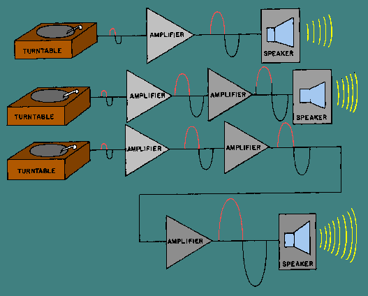
Earlier in this module it was stated that almost every electronic device contains at least one stage of amplification. Many devices contain several stages of amplification and therefore several amplifiers. Stages of amplification are added when a single stage will not provide the required amount of amplification. For example, if a single stage of amplification will provide a maximum gain of 100 and the desired gain from the device is 1000, two stages of amplification will be required. The two stages might have gains of 10 and 100, 20 and 50, or 25 and 40. (The overall gain is the product of the individual stages-10 X 100 = 20 X 50 = 25 X 40 = 1000.) Figure 1-8 shows the effect of adding stages of amplification. As stages of amplification are added, the signal increases and the final output (from the speaker) is increased. Figure 1-8. - Adding stages of amplification.
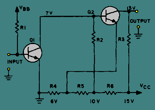
Whether an amplifier is one of a series in a device or a single stage connected between two other devices (top view, figure 1-8), there must be some way for the signal to enter and leave the amplifier. The process of transferring energy between circuits is known as COUPLING. There are various ways of coupling signals into and out of amplifier circuits. The following is a description of some of the more common methods of amplifier coupling. Direct Coupling The method of coupling that uses the least number of circuit elements and that is, perhaps, the easiest to understand is direct coupling. In direct coupling the output of one stage is connected directly to the input of the following stage. Figure 1-9 shows two direct-coupled transistor amplifiers. Figure 1-9. - Direct-coupled transistor amplifiers.
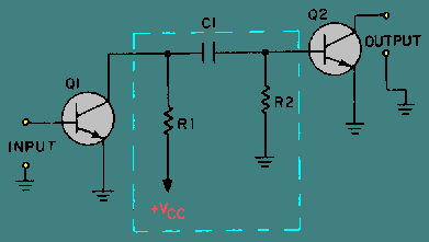
Notice that the output (collector) of Q1 is connected directly to the input (base) of Q2. The network of R4, R5, and R6 is a voltage divider used to provide the bias and operating voltages for Q1 and Q2. The entire circuit provides two stages of amplification. Direct coupling provides a good Frequency response since no frequency-sensitive components (inductors and capacitors) are used. The Frequency response of a circuit using direct coupling is affected only by the amplifying device itself. Direct coupling has several disadvantages, however. The major problem is the power supply requirements for direct-coupled amplifiers. Each succeeding stage requires a higher voltage. The load and voltage divider resistors use a large amount of power and the biasing can become very complicated. In addition, it is difficult to match the impedance from stage to stage with direct coupling. (Impedance matching is covered a little later in this chapter.) The direct-coupled amplifier is not very efficient and the losses increase as the number of stages increase. Because of the disadvantages, direct coupling is not used very often. RC Coupling The most commonly used coupling in amplifiers is RC coupling. An RC-coupling network is shown in figure 1-10. Figure 1-10. - RC-coupled transistor amplifier.
The network of R1, R2, and C1 enclosed in the dashed lines of the figure is the coupling network. You may notice that the circuitry for Q1 and Q2 is incomplete. That is intentional so that you can concentrate on the coupling network. R1 acts as a load resistor for Q1 (the first stage) and develops the output signal of that stage. Do you remember how a capacitor reacts to ac and dc? The capacitor, C1, "blocks" the dc of Q1's collector, but "passes" the ac output signal. R2 develops this passed, or coupled, signal as the input signal to Q2 (the second stage). This arrangement allows the coupling of the signal while it isolates the biasing of each stage. This solves many of the problems associated with direct coupling. RC coupling does have a few disadvantages. The resistors use dc power and so the amplifier has low efficiency. The capacitor tends to limit the low-Frequency response of the amplifier and the amplifying device itself limits the high-Frequency response. For audio amplifiers this is usually not a problem; techniques for overcoming these frequency limitations will be covered later in this module. Before you move on to the next type of coupling, consider the capacitor in the RC coupling. You probably remember that capacitive reactance (XC) is determined by the following formula:
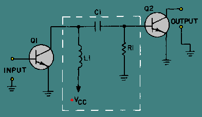
This explains why the low frequencies are limited by the capacitor. As frequency decreases, XC increases. This causes more of the signal to be "lost" in the capacitor. The formula for XC also shows that the value of capacitance (C) should be relatively high so that capacitive reactance (XC) can be kept as low as possible. So, when a capacitor is used as a coupling element, the capacitance should be relatively high so that it will couple the entire signal well and not reduce or distort the signal. Impedance Coupling Impedance coupling is very similar to RC coupling. The difference is the use of an impedance device (a coil) to replace the load resistor of the first stage. Figure 1-11 shows an impedance-coupling network between two stages of amplification. L1 is the load for Q1 and develops the output signal of the first stage. Since the d.c. resistance of a coil is low, the efficiency of the amplifier stage is increased. The amount of signal developed in the output of the stage depends on the inductive reactance of L1. Remember the formula for inductive reactance:
Figure 1-11. - Impedance-coupled transistor amplifier.
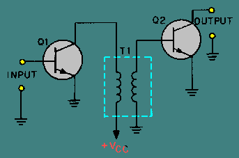
The formula shows that for inductive reactance to be large, either inductance or frequency or both must be high. Therefore, load inductors should have relatively large amounts of inductance and are most effective at high frequencies. This explains why impedance coupling is usually not used for audio amplifiers. The rest of the coupling network (C1 and R1) functions just as their counterparts (C1 and R2) in the RC-coupling network. C1 couples the signal between stages while blocking the d.c. and R1 develops the input signal to the second stage (Q2). Figure 1-12 shows a transformer-coupling network between two stages of amplification. The transformer action of T1 couples the signal from the first stage to the second stage. In figure 1-12, the primary of T1 acts as the load for the first stage (Q1) and the secondary of T1 acts as the developing impedance for the second stage (Q2). No capacitor is needed because transformer action couples the signal between the primary and secondary of T1. Figure 1-12. - Transformer-coupled transistor amplifier.
The inductors that make up the primary and secondary of the transformer have very little dc resistance, so the efficiency of the amplifiers is very high. Transformer coupling is very often used for the final output (between the final amplifier stage and the output device) because of the impedance-matching qualities of the transformer. The Frequency response of transformer-coupled amplifiers is limited by the inductive reactance of the transformer just as it was limited in impedance coupling. Q.12 What is the purpose of an amplifier-coupling network? |
|