Custom Search
|
|
  |
|
|
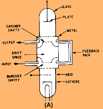
MICROWAVE TUBES Microwave tubes perform the same functions of generation and amplification in the microwave portion of the frequency spectrum that vacuum tubes perform at lower frequencies. This section will explain the basic operation of the most widely used microwave tubes, including klystrons, traveling-wave tubes, backward-wave oscillators, magnetrons, and crossed-field amplifiers. The variations of these tubes for use in specific applications are so numerous that all of them cannot be discussed in this module. However, general principles of operation are similar in all of the variations so the explanations will be restricted to the general principles of operation. The Basic Two-Cavity Klystron Klystrons are velocity-modulated tubes that are used in radar and communications equipment as oscillators and amplifiers. Klystrons make use of the transit-time effect by varying the velocity of an electron beam in much the same manner as the previously discussed velocity-modulation process. Strong electrostatic fields are necessary in the klystron for efficient operation. This is necessary because the interaction of the signal and the electron beam takes place in a very short distance. The construction and essential components of a TWO-CAVITY KLYSTRON are shown in view (A) of figure 2-7. View (B) is a schematic representation of the same tube. When the tube is energized, the cathode emits electrons which are focused into a beam by a low positive voltage on the control grid. The beam is then accelerated by a very high positive dc potential that is applied in equal amplitude to both the accelerator grid and the buncher grids. The buncher grids are connected to a cavity resonator that superimposes an ac potential on the dc voltage. Ac potentials are produced by oscillations within the cavity that begin spontaneously when the tube is energized. The initial oscillations are caused by random fields and circuit imbalances that are present when the circuit is energized. The oscillations within the cavity produce an oscillating electrostatic field between the buncher grids that is at the same frequency as the natural frequency of the cavity. The direction of the field changes with the frequency of the cavity. These changes alternately accelerate and decelerate the electrons of the beam passing through the grids. The area beyond the buncher grids is called the DRIFT SPACE. The electrons form bunches in this area when the accelerated electrons overtake the decelerated electrons. Figure 2-7A. - Functional and schematic diagram of a two-cavity klystron.
Figure 2-7B. - Functional and schematic diagram of a two-cavity klystron.
The function of the CATCHER GRIDS is to absorb energy from the electron beam. The catcher grids are placed along the beam at a point where the bunches are fully formed. The location is determined by the transit time of the bunches at the natural resonant frequency of the cavities (the resonant frequency of the catcher cavity is the same as the buncher cavity). The location is chosen because maximum energy transfer to the output (catcher) cavity occurs when the electrostatic field is of the correct polarity to slow down the electron bunches. The two-cavity klystron in figure 2-7 may be used either as an oscillator or an amplifier. The configuration shown in the figure is correct for oscillator operation. The feedback path provides energy of the proper delay and phase relationship to sustain oscillations. A signal applied at the buncher grids will be amplified if the feedback path is removed. Q.11 What is the basic principle of operation of a klystron? |
 |