Custom Search
|
|
 
|
||
|
CONTROL SYSTEM COMPONENTS The control system commonly uses the components shown in figures 5-35 through 5-43. Table 5-10 provides a brief description of the components and gives their function in the control system. The designations of some components contain number codes which indicate their general location. For
Figure 5-34.-Left side of GCP.
Figure 5-35.-Microswitch.
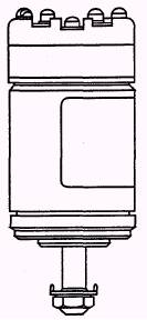
Figure 5-36.-Proximity switch.
Figure 5-37.-Fuses.
Figure 5-38.-Indicating lamp.
Figure 5-39.-Push-button switch.
Figure 5-40.-Toggle switch.
Figure 5-41.-Module. example, the first number in the relay designations used in plug-in modules identifies the module (2J1 through 2J5) containing the relay. A relay with a designation beginning with 4 (4K10, for example) indicates that the relay is located in module 2J4.
Figure 5-42.-Synchro.
Figure 5-43.-Circuit breaker.
Table 5-10.-Control System Components Likewise, for any component designation beginning with a number, the number indicates its general location on the gun mount. A designation beginning with a "1" indicates the component is mounted on a bulkhead; "2" indicates the component is located on the training mass; "3" indicates the component is located on the elevating mass; and "4" indicates the component is mounted on the weather shield. |
 
|
|
|
||