| Tweet |

Custom Search
|
|
 
|
||
|
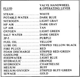
VALVE MANIFOLDS Sometimes suction must be taken from one of many sources and discharged to another unit or units of either the same or another group. A valve manifold is used for this type of operation. An example of such a manifold (fig. 9-31) is the fuel oil filling and transfer system where provision must be made for the transfer of oil from any tank to any other tank, to the service system, or to another ship. If, for example, the purpose is to transfer oil from tank No. 1 to tank No. 4, the discharge valve for tank No. 4 and the suction valve from tank No. 1 are opened, and all other valves are closed. Fuel oil can now flow from tank No. 1, through the suction line, through the pump, through the discharge valve, and into tank No. 4. The manifold suction valves are often of the stop-check type to prevent draining of pumps when they are stopped. VALVE HANDWHEEL IDENTIFICATION AND COLOR CODING Valves are identified by markings inscribed on the rims of the handwheels, by a circular label plate secured by the handwheel nut, or by label plates attached to the ship's structure or to the adjacent piping. Piping system valve handwheels and operating levers are marked for training and casualty control purposes with a standardized color code. Color code identification is in conformance with the color scheme of table 9-1. Implementation of Table 9-1.-Valve Handwheel Color Code
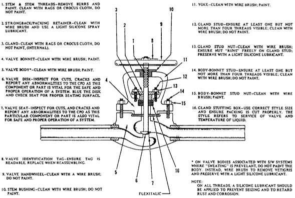
this color scheme provides uniformity among all naval surface ships and shore-based training facilities. MAINTENANCE Preventive maintenance is the best way to extend the life of valves and fittings. Always refer to the applicable portion of the Standard Navy Valve Technical Manual, NAVSEA 0948-LP012-5000, if possible. When making repairs on more sophisticated valve types, use the available manufacturer's technical manuals. As soon as you observe a leak, determine the cause, and then apply the proper corrective maintenance. Maintenance may be as simple as tightening a packing nut or gland. A leaking flange joint may need only to have the bolts tightened or to have a new gasket or O-ring inserted. Dirt and scale, if allowed to collect, will cause leakage. Loose hangers permit sections of a line to sag, and the weight of the pipe and the fluid in these sagging sections may strain joints to the point of leakage. Whenever you are going to install a valve, be sure you know the function the valve is going to perform-that is, whether it must start flow, stop flow, regulate flow, regulate pressure, or prevent backflow. Inspect the valve body for the information that is stamped upon it by the manufacturer: type of system (oil, water, gas), operating pressure, direction of flow, and other information. You should also know the operating characteristics of the valve, the metal from which it is made, and the type of end connection with which it is fitted. Operating characteristics and the material are factors that affect the length and kind of service that a valve will give; end connections indicate whether or not a particular valve is suited to the installation. When you install valves, ensure they are readily accessible and allow enough headroom for full operation. Install valves with stems pointing upward if possible. A stem position between straight up and horizontal is acceptable, but avoid the inverted position (stem pointing downward). If the valve is installed with the stem pointing downward, sediment will collect in the bonnet and score the stem. Also, in a line that is subject to freezing temperatures, liquid that is trapped in the valve bonnet may freeze and rupture it. Since you can install a globe valve with pressure either above the disk or below the disk (depending on which method will be best for the operation, protection, maintenance, and repair of the machinery served by the system), you should use caution. The question of what would happen if the disk became detached from the stem is a major consideration in determining whether pressure should be above the disk or below it. If you are required to install a globe valve, be SURE to check the blueprints for the system to see which way the valve must be installed. Very serious casualties can result if a valve is installed with pressure above the disk when it should be below the disk, or below the disk when it should be above. Valves that have been in constant service for a long time will eventually require gland tightening, repacking, or a complete overhaul of all parts. If you know that a valve is not doing the job for which it was intended, dismantle the valve and inspect all parts. You must repair or replace all defective parts. The repair of globe valves (other than routine renewal of packing) is limited to refinishing the seat and/or disk surface. When doing this work, you should observe the following precautions: When refinishing the valve seat, do not remove more material than is necessary. You can finish valves that do not have replaceable valve seats only a limited number of times. Before doing any repair to the seat and disk of a globe valve, check the valve disk to make certain it is secured rigidly to and is square on the valve stem. Also, check to be sure that the stem is straight. If the stem is not straight, the valve disk cannot seat properly, Carefully inspect the valve seat and valve disk for evidence of wear, for cuts on the seating area, and for improper fit of the disk to the seat. Even if the disk and seat appear to be in good condition, you should perform a spot-in check to find out whether they actually are in good condition. (Figure 9-32) shows a standard checkoff diagram for performing a routine inspection and minor maintenance of a valve. Spotting-In Valves The method used to visually determine whether the seat and the disk of a valve make good contact with each other is called spotting-in. To
Figure 9-32.-Valve maintenance checkoff diagram. spot-in a valve seat, you first apply a thin coating of prussian blue (commonly called Blue Dykem) evenly over the entire machined face surface of the disk. Insert the disk into the valve and rotate it one-quarter turn, using a light downward pressure. The prussian blue will adhere to the valve seat at those points where the disk makes contact. Figure 9-33 shows the appearance of a correct seat when it is spotted-in; it also shows the appearance of various kinds of imperfect seats. After you have noted the condition of the seat surface, wipe all the prussian blue off the disk face surface. Apply a thin, even coat of prussian blue to the contact face of the seat, place the disk on the valve seat again, and rotate the disk onequarter turn. Examine the resulting blue ring on the valve disk. The ring should be unbroken and of uniform width. If the blue ring is broken in any way, the disk is not making proper contact with the seat. |
||
|
||