| Tweet |

Custom Search
|
|
 
|
||
|
Check Valves Check valves are used to allow fluid flow in a system in only one direction. They are operated by the flow of fluid in the piping. A check valve may be the swing type, lift type, or ball type. As we have seen, most valves can be classified as being either stop valves or check valves. Some
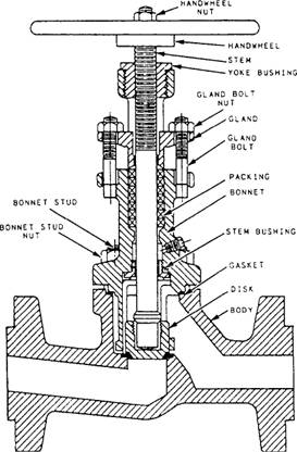
Figure 9-23.-Stop-check valve. valves, however, function either as stop valves or as check valves-depending on the position of the valve stem. These valves are known as STOPCHECK VALVES. A stop-check valve is shown in cross section in figure 9-23. This type of valve looks very much like a lift-check valve. However, the valve stem is long enough so when it is screwed all the way down it holds the disk firmly against the seat, thus preventing any flow of fluid. In this position, the valve acts as a stop valve. When the stem is raised, the disk can be opened by pressure on the inlet side. In this position, the valve acts as a check valve, allowing the flow of fluid in only one direction. The maximum lift of the disk is controlled by the position of the valve stem. Therefore, the position of the valve stem limits the amount of fluid passing through the valve even when the valve is operating as a check valve. Stop-check valves are widely used throughout the engineering plant. Stop-check valves are used in many drain lines and on the discharge side of many pumps. Special-Purpose Valves There are many types of automatic pressure control valves. Some of them merely provide an escape for pressures exceeding the normal pressure; some provide only for the reduction of pressure; and some provide for the regulation of pressure.
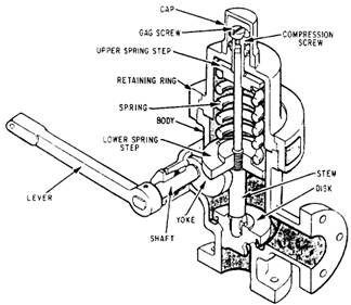
Figure 9-24.-Typical relief valve.
RELIEF VALVES.- Relief valves are automatic valves used on system lines and equipment to prevent overpressurization. Most relief valves simply lift (open) at a preset pressure and reset (shut) when the pressure drops only slightly below the lifting pressure. Figure 9-24 shows a relief valve of this type. System pressure simply acts under the valve disk at the inlet of the valve. When system pressure exceeds the force exerted by the valve spring, the valve disk lifts off its seat, allowing some of the system fluid to escape through the valve outlet until system pressure is reduced to just below the relief set point of the valve. The spring then reseats the valve. An operating lever is provided to allow manual cycling of the relief valve or to gag it open for certain tests. Virtually all relief valves are provided with some type of device to allow manual cycling. Other types of relief valves are the highpressure air safety relief valve and the bleed air surge relief valve. Both of these types of valves are designed to open completely at a specified lift pressure and to remain open until a specific reset pressure is reached-at which time they shut. Many different designs of these valves are used, but the same result is achieved.
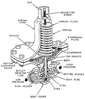
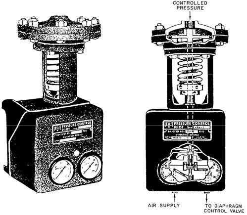
Figure 9-25.-Pressure-reducing (spring-loaded) valve. SPRING-LOADED REDUCING VALVES.Spring-loaded reducing valves, one type of which is shown in figure 9-25 are used in a wide variety of applications. Low-pressure air reducers and others are of this type. The valve simply uses spring pressure against a diaphragm to open the valve. On the bottom of the diaphragm, the outlet pressure (the pressure in the reduced pressure system) of the valve forces the disk upward to shut the valve. When the outlet pressure drops below the set point of the valve, the spring pressure overcomes the outlet pressure and forces the valve stem downward, opening the valve. As the outlet pressure increases, approaching the desired value, the pressure under the diaphragm begins to overcome spring pressure, forcing the valve stem upwards, shutting the valve. You can adjust the downstream pressure by removing the valve cap and turning the adjusting screw, which varies the spring pressure against the diaphragm. This particular spring-loaded valve will fail in the open position if a diaphragm rupture occurs. REMOTE-OPERATING VALVES.-Remoteoperating gear is installed to provide a means of operating certain valves from distant stations. Remote-operating gear may be mechanical, hydraulic, pneumatic, or electric. Some remote-operating gear for valves is used in the normal operation of valves. For example, the main drain system manual valves are opened and closed by a reach rod or a series of reach rods and gears. Reach rods may be used to operate engine-room valves in instances where the valves are difficult to reach from the operating stations. Other remote-operating gear is installed as emergency equipment. Some of the main drain and almost all of the secondary drain system valves are equipped with remote-operating gears. You can operate these valves locally, or in an emergency, you can operate them from remote stations. Remote-operating gear also includes a valve position indicator to show whether the valve is open or closed. PRESSURE-REDUCING VALVES.- Pressurereducing valves are automatic valves that provide a steady pressure into a system that is at a lower pressure than the supply system. Reducing valves of one type or another are found, for example, in firemain, seawater, and other systems. A reducing valve can normally be set for any desired downstream pressure within the design limits of the valve. Once the valve is set, the reduced pressure will be maintained regardless of changes in the supply pressure (as long as the supply pressure is at least as high as the reduced pressure desired) and regardless of the amount of reduced pressure fluid that is used. Various designs of pressure-reducing valves are in use. Two of the types most commonly found on gas turbine ships are the spring-loaded reducing valve (already discussed) and the air-pilot operated diaphragm reducing valve. Air-pilot operated diaphragm control valves are used extensively on naval ships. The valves and pilots are available in several designs to meet different requirements. They may be used to reduce pressure, to increase pressure, as unloading valves, or to provide continuous regulation of pressure. Valves and pilots of very similar design can also be used for other services, such as liquid-level control and temperature control. The air-operated control pilot may be either direct acting or reverse acting. A directacting, air-operated control pilot is shown in figure 9-26. In this type of pilot, the controlled pressure-that is, the pressure from the discharge side of the diaphragm control valve-acts on top of a diaphragm in the control pilot. This pressure is balanced by the pressure exerted by the pilot adjusting spring. If the controlled pressure increases and overcomes the pressure exerted by the pilot adjusting spring, the pilot valve stem is forced downward. This action causes the pilot valve to open, thereby increasing the amount of operating air pressure going from the pilot to the diaphragm control valve. A reverse-acting pilot has a lever that reverses the pilot action. In a reverse-acting pilot, therefore, an increase in controlled pressure produces a decrease in operating air pressure.
Figure 9-26.-Air-operated control pilot.
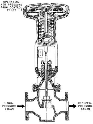
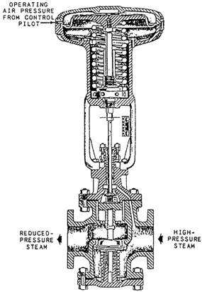
Figure 9-27.-Diaphragm control valve, downward-seating type. In the diaphragm control valve, operating air from the pilot acts on the valve diaphragm. The superstructure, which contains the diaphragm, is direct acting in some valves and reverse acting in others. If the superstructure is direct-acting, the operating air pressure from the control pilot is applied to the TOP of the valve diaphragm. If the superstructure is reverse-acting, the operating air pressure from the pilot is applied to the UNDERSIDE of the valve diaphragm. Figure 9-27 shows a very simple type of directacting diaphragm control valve with operating air pressure from the control pilot applied to the top of the valve diaphragm. Since the valve in the figure is a downward-seating valve, any increase in operating air pressure pushes the valve stem downward toward the closed position. Now look a figure 9-28. This is also a directacting valve with operating air pressure from the control pilot applied to the top of the valve
Figure 9-28.-Diaphragm control valve, upward-seating type. diaphragm. Note that the valve shown in figure 9-28 is more complicated than the one shown in figure 9-27 because of the added springs under the seat. The valve shown in figure 9-28 is an upward-seating valve rather than a downwardseating valve. Therefore, any increase in operating air pressure from the control pilot tends to OPEN this valve rather than to close it. As you have seen, the air-operated control pilot may be either direct acting or reverse acting. The superstructure of the diaphragm control valve may be either direct acting or reverse acting. And, the diaphragm control valve may be either upward seating or downward seating. These three factors, as well as the purpose of the installation, determine how the diaphragm control valve and its air-operated control pilot are installed in relation to each other. To see how these factors are related, let's consider an installation in which a diaphragm control valve and its air-operated control pilot are used to supply controlled steam pressure.
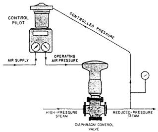
Figure 9-29.-Arrangement of control pilot and diaphragm control valve for supplying reduced-steam pressure. Figure 9-29 shows one arrangement that you might use. Assume that the service requirements indicate the need for a direct-acting, upwardseating diaphragm control valve. Can you figure out which kind of a control pilot-direct acting or reverse acting-should be used in this installation? Try it first with a direct-acting control pilot, As the controlled pressure (discharge pressure from the diaphragm control valve) increases, increased pressure is applied to the diaphragm of the direct-acting control pilot. The valve stem is pushed downward and the valve in the control pilot is opened. This increases the operating air pressure from the control pilot to the top of the diaphragm control valve. The increased operating air pressure acting on the diaphragm of the valve pushes the stem downward, and since this is an upward-seating valve, this action OPENS the diaphragm control valve still wider. Obviously, this won't work for this application. An INCREASE in controlled pressure must result in a DECREASE in operating air pressure. Therefore, we made a mistake in choosing the direct-acting control pilot, For this particular pressure-reducing application, you should choose a REVERSEACTING control pilot. It is not likely that you will be required to decide which type of control pilot and diaphragm control valve is needed in any particular installation. But you must know how and why they are selected so you do not make mistakes in repairing or replacing these units.
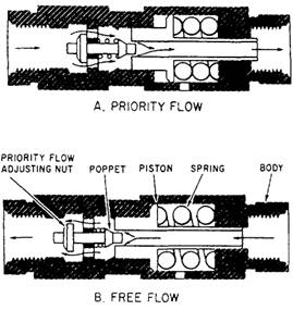
Figure 9-30.-Priority valve. PRIORITY VALVES.- In systems with two or more circuits, it is sometimes necessary to have some means of supplying all available fluid to one particular circuit in case of a pressure drop in the system. A priority valve is often incorporated in the system to ensure a supply of fluid to the critical/vital circuit. The components of the system are arranged so the fluid to operate each circuit, except the one critical/vital circuit, must flow through the priority valve. A priority valve may also be used within a subsystem containing two or more actuating units to ensure a supply of fluid to one of the actuating units. In this case, the priority valve is incorporated in the subsystem in such a location that the fluid to each actuating unit, except the critical/vital unit, must flow through the valve. Figure 9-30 shows one type of priority valve. View A of figure 9-30 shows the valve in the priority-flow position; that is, the fluid must flow through the valve in the direction shown by the arrows to get to the noncritical/vital circuits or actuating units. With no fluid pressure in the valve, spring tension forces the piston against the stop and the poppet seats against the hole in the center of the piston. As fluid pressure increases, the spring compresses and the piston moves to the right. The poppet follows the piston, sealing the hole in the center of the piston until the preset pressure is reached. (The preset pressure depends upon the requirements of the system and is set by the manufacturer.) Assume that the critical/ vital circuit or actuating unit requires 1500 psi.
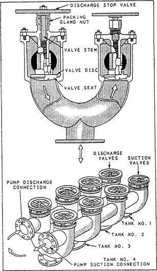
Figure 9-31.-Valve manifold showing cutaway view of the valves and typical combination of suction and discharge valves. When the pressure in the valve reaches 1500 psi, the poppet reaches the end of its travel. As the pressure increases, the piston continues to move to the right, which unseats the poppet and allows flow through the valve, as shown in view A of figure 9-30. If the pressure drops below 1500 psi, the compressed spring forces the piston to the left, the poppet seats, and flow through the valve stops. Figure 9-30 view B, shows the priority valve in the free-flow position. The flow of fluid moves the poppet to the left, the poppet spring compresses, and the poppet unseats. This allows free flow of fluid through the valve. |
||
|
||