Custom Search
|
|
 
|
||
|
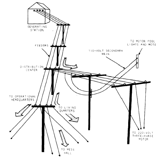
Figure 9-5 shows a Y-connected alternator (three-phase,
four-wire). N represents a common or
NEUTRAL point to which the stator coils are all
connected. The current is taken off the stator by
the three lines (wires), 1, 2, and 3, connected to
the stator coil ends; and also by a fourth line, N,
connected to the neutral point. Lines 1, 2, and 3
are hot wires; line N is NEUTRAL. The voltage developed in any pair of wires, or in all three wires, in a delta-connected alternator is always the same; therefore, a
Figure 9-6.-A pictorial view of a four-wire overhead distribution system. delta-connected system has only a single voltage rating (220 V in fig. 9-4). However, in a Y-connected system, the voltage developed in different combinations of wires is different. In figure 9-5, you can see that lines 1 and 2 take power from two stator coils (A and C). The same applies to lines 1 and 3 (power from coils C and B) and lines 2 and 3 (power from coils A and B). However, the neutral (N) and line 2 take power from coil A only; neutral (N) and line 1, from coil C only; and neutral (N) and line 3, from coil B only.It follows from this that a Y-connected alternator can produce two different voltages: a higher voltage in any pair of hot wires, or in all three hot wires, and a lower voltage in any hot wire paired with the neutral wire.Output taken from a pair of wires is SINGLE-PHASE voltage; output from three wires isTHREE-PHASE voltage. The practical significance of this lies in the fact that some electrical equipment is designed to operate only on single-phase voltage, while other equipment is designed to operate only on three-phase voltage. This equipment includes the alternators them-selves, and a system with a three-phase alternator is called a three-phase system. However, even in such a system, single-phase voltage can be obtained by tapping only two of the wires. Figure 9-6 shows a four-wire system serving the same facilities. Here there is a Y-connected alternator rated at 110/220 V. You can see that to get 110 V single phase for the secondary mains, no transformers are necessary. These mains are simply tapped into pairs of wires, one of each pair being a hot wire and the other, the neutral wire. The 220-V, three phase motor is tapped into the three hot wires that develop 220 V, three-phase. You can see that the neutral wire in a four-wire system exists to make it possible for a lower voltage to be used in the system.Figure 9-7 shows a wiring diagram for the system shown in figure 9-6.Now, lets discuss the device called a DISTRIBUTION TRANSFORMER. A transformer is simply a device for increasing or reducing the voltage in an electrical circuit. It ranges in size from one that is portable (those used for appliances inside the building) to heavy ones that are mounted permanently on platforms or Figure 9-7.-Wiring diagram of the four-wire system in figure 9-6. hung with crossarm brackets attached to an electric pole. Ask one of the CES to show you a transformer. It is very probable that one is nearby. Now, for long-distance power transmission, a voltage higher than that normally generated is required. A transformer is used to step the voltage up to that required for transmission. Then at the service distribution end, the voltage must be reduced to that required for lights and equipment. Again a transformer is used; but this time it is to step down the voltage. The reason for stepping up the voltage in a line lies in the fact that the greater the distance, the more resistance there will be to the current flow; and a much greater force will be required to push the current through the conductor. Perhaps you can best understand this reasoning if you examine Ohms Law.
(Refer to chapter 1 of this book.) |
 
|
|
|
||