Custom Search
|
|
 
|
||
|
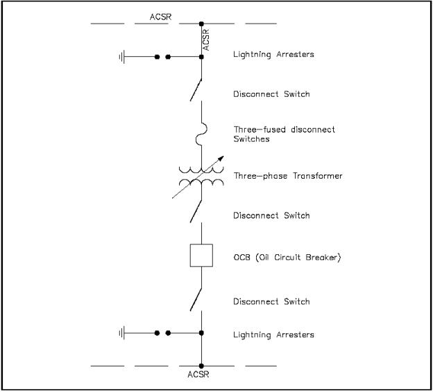
The one-line, or single-line, diagram shows the components of a circuit by means of single lines and the appropriate graphic symbols. One-line diagrams show two or more conductors that are connected between components in the actual circuit. The one-line diagram shows all pertinent information about the sequence of the circuit, but does not give as much detail as a schematic diagram. Normally, the one-line diagram is used to show highly complex systems without showing the actual physical connections between components and individual conductors. As an example, Figure 10 shows a typical one-line diagram of an electrical substation.
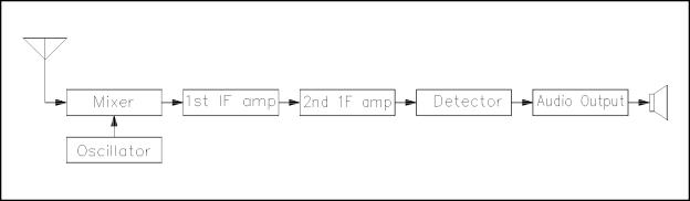
Figure 10 One-Line Diagram A block diagram is used to show the relationship between component groups, or stages in a circuit. In block form, it shows the path through a circuit from input to output (Figure 11). The blocks are drawn in the form of squares or rectangles connected by single lines with arrowheads at the terminal end, showing the direction of the signal path from input to output. Normally, the necessary information to describe the stages of components is contained in the blocks.
Figure 11 Block Diagram
|
||
|
||