Custom Search
|
|
 
|
||
|
Diagram A wiring diagram is a very simple way to show wiring connections in an easy-to-follow manner. These types of diagrams are normally found with home appliances and automobile electrical systems (Figure 12). Wiring diagrams show the component parts in pictorial form, and the components are identified by name. Most wiring diagrams also show the relative location of component parts and color coding of conductors or leads.
Figure 12 Wiring Diagram Resistivity Resistivity is defined as the measure of the resistance a material imposes on current flow. The resistance of a given length of conductor depends upon the resistivity of that material, the length of the conductor, and the cross-sectional area of the conductor, according to Equation (2-1).
where
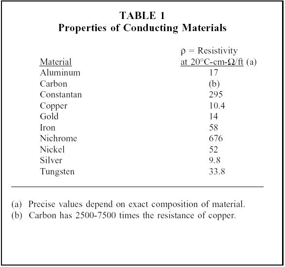
The resistivity p (rho) allows different materials to be compared for resistance, according to their nature, without regard to length or area. The higher the value of p, the higher the resistance. Table 1 gives resistivity values for metals having the standard wire size of one foot in length and a cross-sectional area of 1 cm.
|
||
|
||