Custom Search
|
|
 
|
||
|
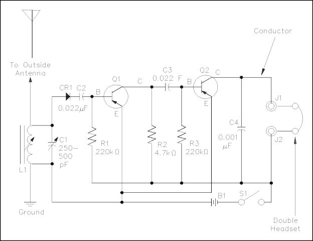
Before operations with DC circuits can be studied, an understanding of the types of circuits and common circuit terminology associated with circuits is essential. EO 1.4 Given a diagram, IDENTIFY it as one of the following types: a. Schematic diagram b. One-line diagram c. Block diagram d. Wiring diagram EO 1.5 DEFINE the following terms: a. Resistivity b. Temperature coefficient of resistance c. Closed circuit d. Open circuit e. Short circuit f. Series circuit g. Parallel circuit h. Equivalent resistance EO 1.6 Given a circuit, DETERMINE whether the circuit is an open circuit or a closed circuit. Schematic Diagram Schematic diagrams are the standard means by which we communicate information in electrical and electronics circuits. On schematic diagrams, the component parts are represented by graphic symbols, some of which were presented earlier in Module 1. Because graphic symbols are small, it is possible to have diagrams in a compact form. The symbols and associated lines show how circuit components are connected and the relationship of those components with one another. As an example, let us look at a schematic diagram of a two-transistor radio circuit (Figure 9). This diagram, from left to right, shows the components in the order they are used to convert radio waves into sound energy. By using this diagram it is possible to trace the operation of the circuit from beginning to end. Due to this important feature of schematic diagrams, they are widely used in construction, maintenance, and servicing of all types of electronic circuits.
Figure 9 Schematic Diagram
|
 
|
|
|
||