Custom Search
|
|
 
|
|||||||||||||||||||||||||||||||||||||||||||||||||||||
|
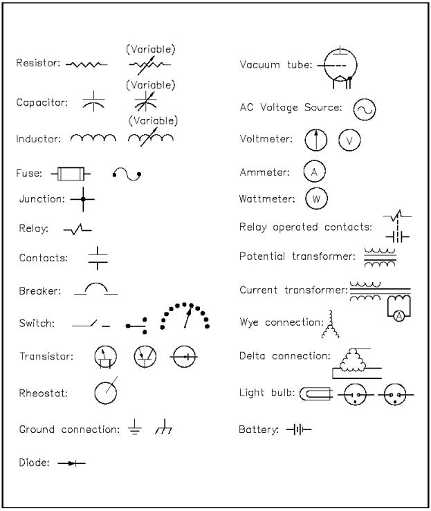
To read and interpret electrical system diagrams and schematics, one must be thoroughly familiar with the many symbols used. Once these symbols are mastered, most electrical diagrams and schematics will be understood with relative ease. EO 1.14 Given a standard electrical symbol, IDENTIFY the component that the symbol represents. The symbols will be for the following components:
Svmbols The symbols for the various electrical components that will appear on electrical diagrams and schematics are shown in Figure 30. Basic Electrical Theory
Figure 30 Electrical Symbols Summary The important information contained in this chapter is summarized below. Electrical Symbols Summary To read and interpret electrical system diagrams and schematics, one must be thoroughly familiar with the many symbols used. Once these symbols are mastered, most electrical diagrams and schematics will be understood with relative ease.
|
|||||||||||||||||||||||||||||||||||||||||||||||||||||
|
|||||||||||||||||||||||||||||||||||||||||||||||||||||