TM 5-4240-501-14P
IGNITION
FLYWHEEL TYPE—INTERNAL BREAKER
Removing Breaker Cover
Care should be taken when removing breaker cover, to
avoid damaging cover. If cover is bent or damaged it
should be replaced to insure a proper dust seal.
Breaker Points
Breaker point gap on all models is .020" (0.5 mm).
Breaker points should be checked for contact and for
signs of burning or pitting. Points set too wide will
advance spark timing and may cause kick back when
starting. Points gapped too close retard spark timing and
decrease engine power.
Remove Breaker Points
Breaker point assemblies of style shown in Fig. 13 are
removed by removing condenser and armature wires
from breaker points clip. Loosen adjusting lock screw
and remove breaker point assembly.
Breaker point assemblies of style shown in Fig. 14 are
removed by loosening the screw holding the post. The
condenser on these models also includes the breaker
point. The condenser is removed by loosening the screw
holding the condenser clamp.
Fig. 13 - Breaker Point Assemblies
Fig. 14 - Breaker Point Assemblies
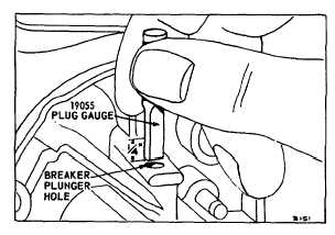
Check Breaker Point Plunger Hole
Fig. 15 - Checking Breaker Plunger Hole
If the breaker point plunger hole becomes worn
excessively, oil will leak past the plunger and may get on
the points, causing burning. To check, loosen breaker
point mounting screw and move breaker points out of the
way. Remove plunger. If the flat end of the 19055 plug
gauge will enter the plunger hole for a distance of 1/4"
(6.35 mm) or more, the hold should be rebushed: Fig.
15.
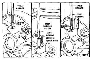
Install Breaker Point Plunger Bushing
To install the bushing, it is necessary that the breaker
points, armature, crankshaft and starter be removed.
Use reamer 19056, to ream out the old plunger hole.
See Fig. 16. This should be done by hand. The reamer
should be in alignment with the plunger hole. Drive the
bushing 23513, with driver 19057 until the upper end of
the bushing is flush with the top of the boss. Fig. 16.
Finish ream the bushing with reamer 19058. All reaming
chips or dirt must be removed.
Fig. 16 - Installing Breaker Plunger Bushing
2
5