IGNITION
Flywheel Type - MAGNETRONTM - Internal Breaker
IGNITION
Flywheel Type - Internal Breaker
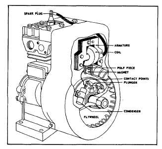
The flywheel is located on the crankshaft with a soft
metal key. It is held in place by a nut or starter clutch.
The flywheel key must be in good condition to insure
proper location of the flywheel for ignition timing. DO
NOT use a steel key under any circumstances. Use only
the soft metal key, as originally supplied.
The keyway in both flywheel and crankshaft should not
be distorted. Flywheels used are made of aluminum,
zinc or cast iron.
Fig. 4 - Flywheel Ignition Internal Breaker
REMOVING ARMATURE AND
MAGNETRONTM IGNITION
The flywheel does not need to be removed to service
MAGNETRONTM except to check keyways and flywheel
key.
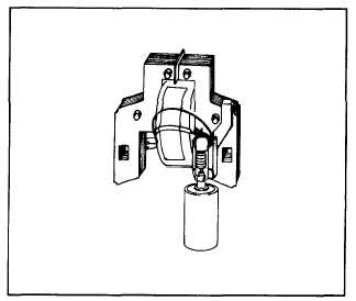
Remove armature screws and lift off armature Use
breaker point condenser P/N 294628 or 3/16" pin punch
to release stop switch wire from MAGNETRON" module.
Fig. 5. Stop switch wire is soldered to module and
armature primary wires. Unsolder to disconnect.
Fig. 5 - MAGNETRON’" Module
REMOVING MAGNETRON
TM
MODULE
Unsolder armature ground wire from module wire, Fig. 6.
Remove tape and move module ground wire to clear
armature coil and laminations. Push module retainer
away from laminations and push module off laminations,
Fig. 7.
Fig. 6 -
Fig. 7 -
2
3