
TM 3-4240-302-30&P-5
2-7. POWER DISTRIBUTION UNIT (CONT).
LOCATION
ITEM
ACTION
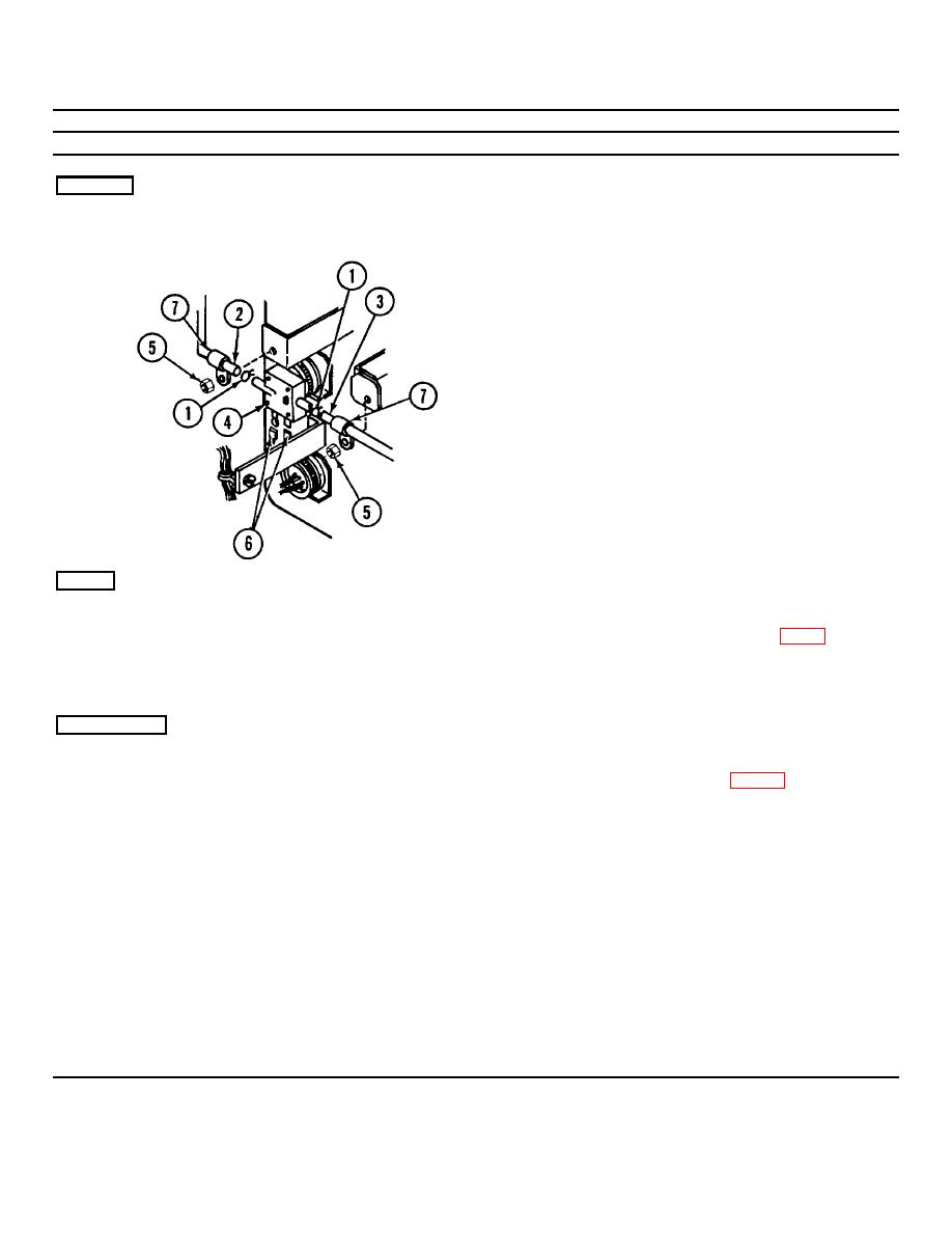
REMOVAL
Panel
Pressure switch S7
1.
Loosen nuts (5).
2.
Remove loop clamps (7).
3.
Pinch ears of hose clamps (1), and remove
tubing (2 and 3) from pressure switch S7 (4).
4.
Disconnect electrical connectors (6) from
pressure S7 (4) switch, and remove switch.
NOTE
Observe orientation of pressure switch for
installation.
REPAIR
Nonmetallic tubing
Replace tubing if torn or broken. Fabricate
replacement tubing (2 or 3) from item 1, app B,
bulk material. Cut to same length as tubing being
replaced.
INSTALLATION
Pressure switch S7
1.
Connect wire connectors to pressure switch S7
(4). Refer to wiring diagram (p. 2-39).
2.
Position pressure switch S7 (4) between tubing
(2 and 3) with switch terminals pointing toward
transformer/rectifier T1 and LOW and HIGH
marking away from panel.
3.
Install tube (3) on LOW side of switch and
tube (2) on HIGH side.
4.
Position clamps (1) within 1/4 inch of switch
body.
4.
Replace loop clamps (7).
6.
Tighten nuts (5).
2-32

