Click here to make tpub.com your Home Page

Page Title: Chapter 3. OPERATING INSTRUCTIONS
Back | Up | Next

Click here for thousands of PDF manuals

Google


Web
www.tpub.com

Home


Information Categories
.... Administration
Advancement
Aerographer
Automotive
Aviation
Construction
Diving
Draftsman
Engineering
Electronics
Food and Cooking
Logistics
Math
Medical
Music
Nuclear Fundamentals
Photography
Religion


Back
Figure 2-2. Tube locations, Spectrum Analyzer TS-729(*)/U.
Up
TM-11-6625-255-14
Next
Figure 3-2. Front panel controls and indicators, Spectrum Analyzers TS-723B/U, TS-723C/U, and TS-723D/U.

TM 11-6625-255-14/TO 33A1-13­170­1
CHAPTER 3
OPERATING INSTRUCTIONS
Section I. CONTROLS AND INSTRUMENTS
3­2. Operator Controls
3­1. Damage from Improper Settings
Table 3-1 lists the controls and indicators used by
To prevent the equipment from damage as a re-
the operator, together with their functions. Front
suit of improper settings, observe the following
panel controls are illustrated in figures 3-1 and
precautions when setting the controls:
3-2. Rear panel views of all models are shown in
a. Turn the signal AF INPUT control to MIN.
b. Set the meter range switch to +50 DB. This
protects the meter pointer from being damaged in
case of violent deflection.
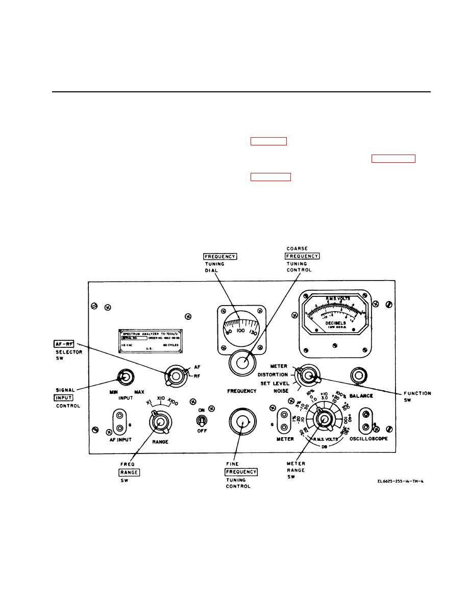
Figure 3-1. Front panel controls and indicators, Spectrum Analyzer TS-723A/U.
3-1

Privacy Statement - Press Release - Copyright Information. - Contact Us