
(4) increase voltage output of test generator.
(2) Adjust R7801 (figure 2) so that RED in-
GREEN indicator on unit under test should glow
dicator glows when electronic voltmeter indicates
when Electronic Voltmeter
(A4) indicates be-
13.5 volts. (R)
tween 2.60 and 3.30 volts.
Note. Repeat steps (1) and (2) until both GREEN
and RED indicators operate properly.
(5) Reduce output voltage of test generator to
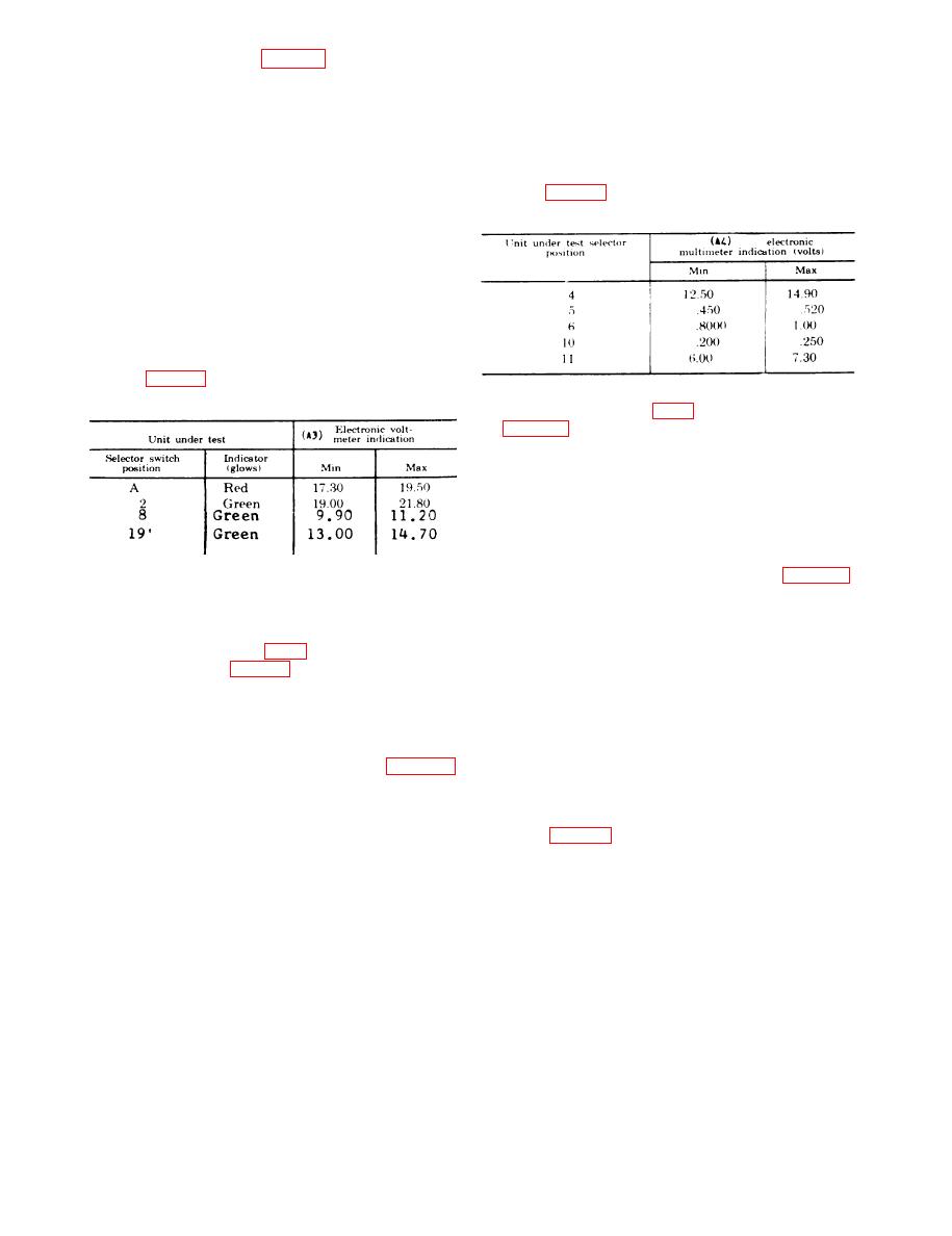
10. Dc Circuits.
0 (zero).
a. Performance Check.
(6) Repeat steps (2) through (5) using values
(1) Turn unit under test selector switch to
listed in table 4.
position A.
Table 4. Audio Circuit Values
(2) Vary dc output voltage of Power Supply
(A7) from 0 to 21 volts.
(3) GREEN indicator on unit under test
should glow when electronic voltmeter indicates be-
tween 13.40 and 15.00 volts.
(4) Reduce dc output voltage of power supply
to 0 (zero).
(5) Repeat steps (1) through (4) using values
listed in table 3.
b. Adjustments.
Table 3. Dc Circuit Values
(1) Adjust R7406 (fig. 2) for indications listed
in table 4. (R)
(2) If R7406 is adjusted for the 4, 5, 6, 10,
or 11 position, the previous voltage checks in this
table must be rechecked until all indications are
within the prescribed tolerances.
12. RF Circuits.
a. Performance Check.
Earlier models of AN/VRM-1, position 19
(1) Connect equipment as shown in figure 6.
i s not used.
(2) Turn selector switch of unit under test to
position 12.
b. Adjustments.
(3) Adjust frequency output of Signal Gen-
(1) Adjust R7501 (fig. 2) for the A selector
erator (A8) for an indication of 5.65
indication listed in table 3. (R)
MHz 1 kHz as determined by Electronic
(2) No adjustment for correction of indication
C o u n t e r (A5).
received at switch positions 2, 8, 19 can be made.
(4) Increase voltage output of signal gener-
11. Audio Circuits.
ator. GREEN indicator on unit under test should
a. Performance Check.
glow when Electronic Multimeter
(A2)
in-
(1) Connect equipment as shown in figure 5.
d i c a t e s between 0.125 and 0.250 volt ac.
(2) Turn selector switch of unit under test to
(5) Reduce output voltage of signal generator,
3 position.
(6) Repeat steps (2) through (5) using values
(3) Adjust Audio Level Test Generator
listed in table 5.
( A 1 ) for 1 kHz output.
8

