
7. Preliminary Procedure.
a. Remove protective cover from unit under test.
RED indicator glows when electronic voltmeter in-
b. Set unit under test power switch to ON.
dicates 21.5 volts dc as dc power supply is varied
from 0 to 26 volts. (R)
9. Voltage Sensing Circuit.
Note. The following paragraphs are divided into sub-
paragraph a , performance check and subparagraph b ,
a. Performance Check.
adjustments. W h e n the performance check is within
(1) Connect equipment as shown in figure 4.
tolerance, do not perform the corresponding adjustment.
(2) Turn unit under test selector switch to
When the performance check is not within tolerance,
perform the corresponding adjustment before continuing
position 8.
with the calibration procedure. When the performance
(3) Vary dc output of Power Supply (A7)
c h e c k is not within tolerance and no adjustment is
from 0 to 15 volts.
specified, the deficiency must be corrected before con-
(4) RED indicator on unit under test should
tinuing with the procedure.
cease to glow and GREEN indicator should glow
8. Power Test.
when electronic voltmeter indicates between 9.9 and
a. Performance Check.
11.2 volts. RED indicator should glow when elec-
(1) Connect equipment as shown in figure 3.
tronic voltmeter indicates between 12.7 and 14.2
(2) With unit under test power switch set to
volts.
from
(A6)
ON, vary DC POWER SUPPLY
b. Adjustments.
0 to 26 volts, RED indicator on unit under test
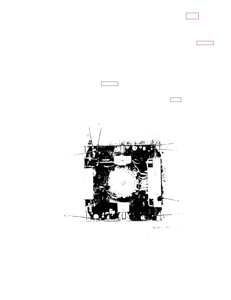
(1) Adjust R7803 (fig. 2) so that GREEN
(A3)
should glow when Electronic Voltmeter
indicator on unit under test glows when electronic
indicates between 21.0 and 22.0 volts dc.
voltmeter indicates 10.5 volts. (R)
Figure 2. Radio Test Set AN/VRM-1 -- rear view.
5

