
TM 5-6115-465-12
TO 35C2-3-446-1
NAVFAC P-8-625-12
TM 06858B/06859D-12
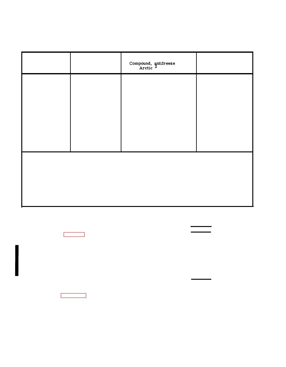
Freezing Points, Composition and Specific Gravities
of Military Anti-freeze Materials
Ethylene glycol coolant
Pints of inhibited
solution specific
glycol per gal. of
Lowest expect ed
gravity at 68F3
coolant 1
ambient temp. F
1.022
Issued full strength and ready
+20
1-1/2
1.036
2
mixed for 0 to -65F
+10
1.047
temperatures for both
2-3/4
0
1.055
3-1/4
initial installation and
-10
1.062
3-1/2
replenishment of losses.
-20
1.067
4
-30
1.073
4-1/4
-40
DO NOT DILUTE WITH WATER
-50
Arctic anti-freeze
-60
preferred
OR ANY OTHER SUB-
STANCE.
-75
1
Maximum protection is obtained at 60 percent by volume (4.8 pints of ethylene glycol per gallon of
solution.
2
Military Specification MIL-C-11755 Arctic type, nonvolatile anti-freeze compound is intended for use in
the cooling system of liquid-cooled internal combustion engines. It is used for protection against freezing
primarily in Arctic regions where the ambient temperature remains for extended periods close to -40F
or drops below, to as low as -90F.
3
Use an accurate hydrometer. To test hydrometer, use 1 part ethylene glycol anti-freeze to 2 parts
water. This should produce a hydrometer reading of 0oF .
WARNING
(b) Fill the cooling system with cool-
ant as specified in table 2-1 and replace cap.
When filling the fuel tank, maintain metal-
to-metal contact between the fuel tank
filler neck and the fuel nozzle to prevent
sparks from static electricity. There
shall be no smoking or open flames in the
vicinity of the fueling operation.
CAUTION
(3) Fuel System.
JP-4 fuel is considered an emergency fuel
only.
(a) Check to see that the fuel tank
drain valve (84, figure 3-22) is closed and the cap
is installed.
(c) Fill the fuel tank with fuel.
(d) Install the fuel tank filler cap.
(b) Remove the fuel tank filler cap.
Change 12

