Click here to make tpub.com your Home Page

Page Title: Figure 4-2. Powerplant Installed on Test Stand
Back | Up | Next

Click here for thousands of PDF manuals

Google


Web
www.tpub.com

Home


Information Categories
.... Administration
Advancement
Aerographer
Automotive
Aviation
Construction
Diving
Draftsman
Engineering
Electronics
Food and Cooking
Logistics
Math
Medical
Music
Nuclear Fundamentals
Photography
Religion


Back
Figure 4-1. M113A3/M548A3 Powerplant
Up
TB-9-2350-368-25 Fabrication and Operation of Powerplant Test Stand Manual
Next
Figure 4-3. Bleeder Hose Assembly

TB 9-2350-368-25
NOTE
See Figure 4-8 for partial guide and check list of items to be
connected.
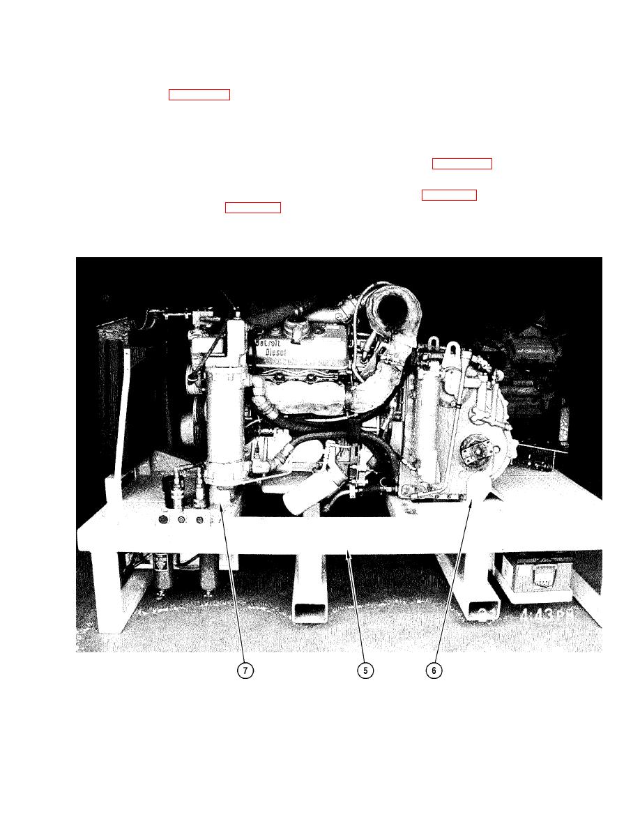
3. Place powerplant assembly (4) on powerplant test stand (5). Have helper assist.
4. Check that powerplant (4) is position within transmission brackets (6) (Figures 2-6 and 2-7) and firmly
supported.
5. Secure engine front mount to powerplant test stand front mount (7) (Figure 2-6) with two screws, four
washers, and two nuts. See Figure 4-2.
Figure 4-2. Powerplant Installed on Test Stand

Privacy Statement - Press Release - Copyright Information. - Contact Us