
MWO 9-2330-390-25-1
APPENDIX C:
TOP AND BOTTOM BEAM AND HYDRAULIC LIFT
CYLINDER REMOVAL / INSTALLATION (Con't).
12. Slide one of the upper vertical tubes (34 or 35) over an assembled lower vertical tube
Proper assembly will have the stability cable mount positioned outboard and to the
container mounting surface.
NOTE
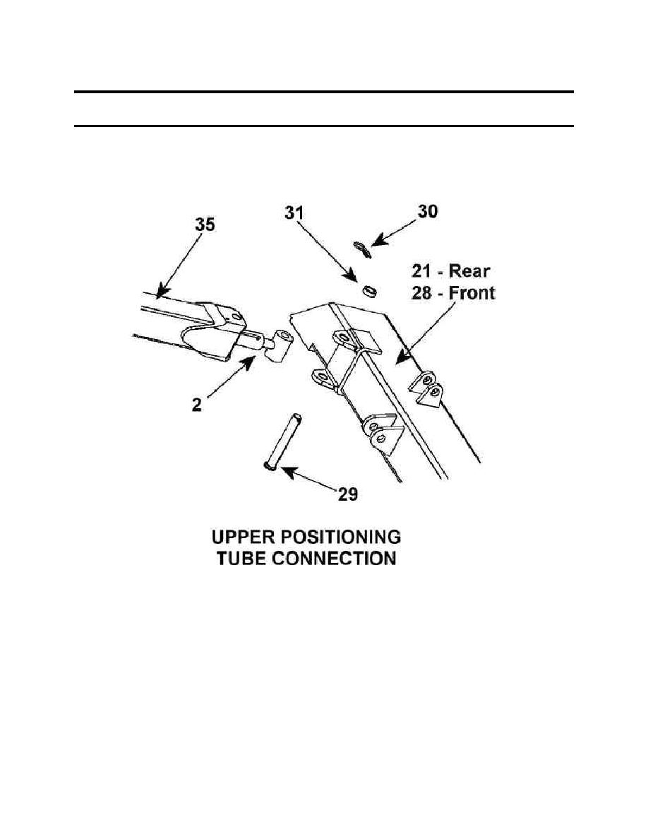
Ensure that the hole at rod end of positioning cylinder is aligned with hole in top
beam.
To ensure proper assembly install items (29), (30), (31) as illustrated above.
13. Insert clevis pin (29) into upper vertical tube (34 or 35), tube mounting tabs on the upper
beam (21 Rear, 28 - Front), and the positioning cylinder rod end (2).
14. Add spacer (31) to free end of clevis pin (29).
15. Insert cotter pin (30) to complete upper tube connection.
16. Repeat steps 12 though 15 to complete second upper tube connection.
C-7

