Custom Search
|
|
 
|
||
|
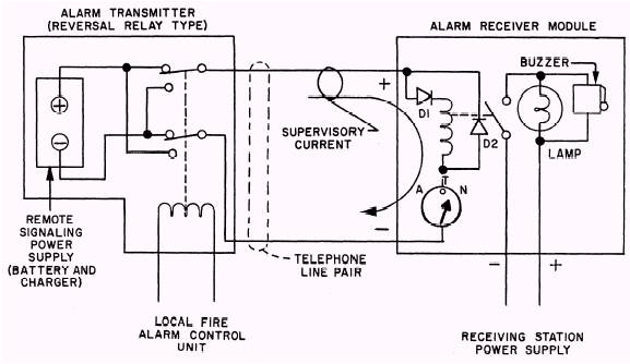
Auxiliary Devices A building alarm system control unit may have auxiliary contacts that operate auxiliary functions when an alarm occurs. For auxiliary devices, the power source can be either the main fire alarm power supply or line power, if battery standby power is not required for the auxiliary functions. A failure of auxiliary functions should not adversely affect the primary function of the alarm system, which is to warn the occupants of a threat of fire. One auxiliary function included in the majority of fire alarm systems today is the heating, ventilation, and air conditioning (HVAC) fan shutdown. Auxiliary contacts are connected into the motor starter circuit for each fan that is to be shut down upon alarm. It may be more convenient to use an alarm voltage output from the control unit to cause fan shutdown. A relay with multiple contacts (a multipole relay) for controlling multiple fans is located near the motor control center or the temperature control panel. The relay coil is energized by alarm voltage from the alarm control unit, causing contacts to open in the individual
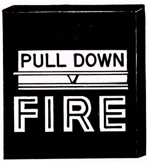
Figure 7-5.\Typical remote alarm signaling circuit. fan control circuits, thereby stopping all the fans. Other auxiliary devices controlled by the alarm system can perform the following functions: fire door closure, ventilation louver closure, and/or release of extinguishing agent. Consult the manufacturer's literature and/or base blueprints to determine the options included in your fire alarm system. ALARM-INITIATING DEVICES An alarm device initiates a fire alarm signal either as a result of manual operation, such as a manual fire alarm station, or automatically, as in the case of heat, smoke, flame, or water-flow detectors. Initiating devices, with rare exceptions, have normally open contacts that close on an alarm condition. Normally closed devices are intended only for such applications as operating the shutdown control for fans or other auxiliary devices. Manual Fire Station Figure 7-6 shows a manual fire station, which is also called a manual pull box, a manual firebox,
Figure 7-6.\Manual pull box. or a manual fire alarm. A manual fire alarm system may include many initiating devices. The manual fire alarm devices are to provide a means of manually activating the fire alarm system. They are used in all types of fire alarm systems. They may be the only type of initiating devices provided or they may be used with automatic initiating devices, such as heat or smoke detectors. Manual fire stations are generally located near main exits from a building or from a floor of a multistory building and in certain work areas containing unusual fire hazards, valuable equipment, or records subject to fire damage. Paint shops, aircraft repair areas, computer rooms, and telephone equipment rooms are examples of such work areas. Single-action and double-action devices are both used. The single-action device requires one action to cause an alarm, and a replaceable glass rod is broken with each operation. The doubleaction device requires two actions to cause an alarm: first, the glass window is broken; second, the alarm lever is pulled. The glass elements in these two examples are necessary parts to retain all the design features. Both devices can be tested without breaking the glass parts by opening the device. To open a manual fire alarm box, you may have to loosen a setscrew or operate a latch with a hexagonal (allen) wrench, screwdriver, or key. Manual initiating devices should be visually inspected monthly for physical damage, such as that caused by vandalism or painting. At this time, count the devices to be sure that none have been concealed or removed. Correct deficiencies promptly. Test repaired units by mechanical operation and transmission of local and remote signals without glass breakage. Be sure to inform building and fire department personnel that the test is to be performed. Test all manual devices on a rotation schedule so that all devices are tested semiannually. Some devices should be tested each month, at least one from each initiating circuit (zone) or remote signaling circuit, in the case of coded fire alarm boxes. Keep accurate records of devices tested, their locations, and the rotation scheme. Store a copy of building system diagrams and test records in the control unit.
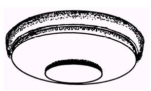
Figure 7-7.\Low-profile heat protector. |
||
|
||