Custom Search
|
|
 
|
||
|
Remote Alarm Signaling Because of excitement, a lack of knowledge, or a lack or responsible personnel on the premises, people frequently do not react properly to a local fire alarm signal. Therefore, it is usually desirable to connect building alarm systems to a remote receiving station manned at all times by competent personnel who can take the proper action-to extinguish the fire and evacuate the building if necessary or to see that necessary maintenance is completed. Most fire alarm and supervisory alarm control panels have provision for connection to a remote receiving station. These connections are usually in the form of auxiliary relay contacts that can be connected to operate an alarm transmitter.
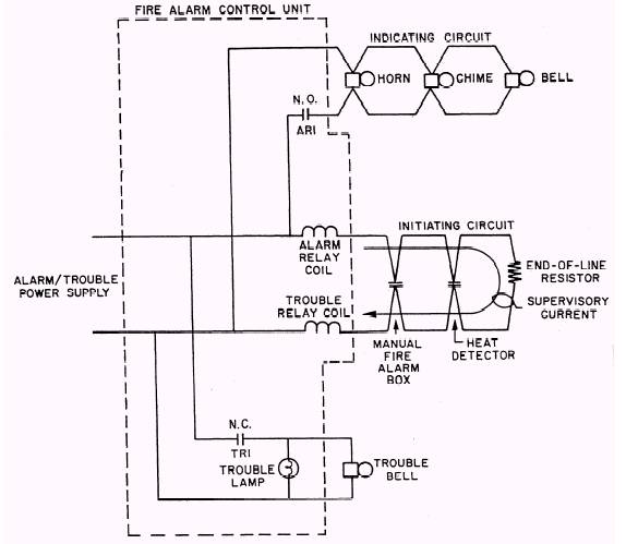
Figure 7-4.\Typical local alarm signaling circuit.
Figure 7-5 shows a typical remote alarm signaling circuit, a commonly used arrangement for fire department connection to individual building alarm systems. The alarm transmitter can either be a part of the fire alarm control cabinet or be operated by it. If, instead of a fire condition occurring, one of the two telephone wires is broken, the supervising current supplied by the transmitter will drop to zero, closing the receiver module relay contacts, lighting the lamp, and sounding the buzzer. The meter indication will be zero, marked on the meter face as "T" (trouble). If a telephone wire is broken before an alarm condition occurs, the voltage will be reversed by the alarm transmitter, but the "no current" condition at the alarm receiver will not be changed, and no alarm will be caused. The trouble condition will continue until the broken wire is repaired. In the circuit shown in figure 7-5, if an alarm condition occurs, the transmitter contacts transfer, reversing voltage and current polarity of the telephone line pair. The meter in the receiver module changes indication from N (normal) to A (alarm). Current flow through the receiver module relay is blocked by diode D1, and the receiver module relay contacts close, lighting the lamp and sounding the buzzer. The current for meter alarm indication flows through the meter and diode D2. |
||
|
||