Custom Search
|
|
  |
|
|
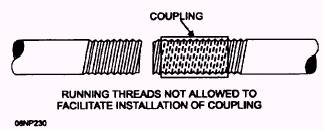
CONDUIT INSTALLATION In previous sections we have discussed types of conduits and the cutting, threading, and bending of conduit. Now, we will cover the requirements for installing the different types of conduit and how conductors should be pulled into them. Several general requirements apply to all types of conduit installation: All raceways must be installed as a complete system before any conductors are pulled into them. In other words, the "run" of conduit, as described previously, including conduit, fitting, and supports, must be complete before the conductors are installed. A run of conduit should be as straight and direct as possible. When a number of conduit runs are to be installed parallel and adjacent to each other, you should install them all at the same time. The minimum-sized raceway that can be installed generally is 1/ 2-inch electrical trade size. Specific exceptions to this rule
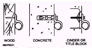
Figure 5-52.- Running threads. include EMT, rigid, and flexible conduit installed in specific locations. The exceptions for each type are outlined in the NEC(c). All types of conduit must be reamed after they have been cut. Conduit threaded in the field must be threaded with a die that has a 3/ 4-inch taper per foot. When threaded conduit enters a box or fitting, a bushing must be used to protect the conductor insulation from being cut or tom. Also, for those types that use threaded couplings, running threads, as shown in figure 5-52, are not to be used for connection at couplings. Running threads weaken the conduit and may come loose. Threaded couplings and connectors used with any type of conduit must be made up tight. Couplings or connectors that are to be buried in concrete or masonry have to be the concrete-tight type; those to be installed in wet locations have to be the raintight type. Conduit must be supported by straps or hangers throughout the entire run. Figure 5-53 shows how straps are fastened on different types of surfaces. On a wooden surface, nails or wood screws can be used to secure the straps. On brick or concrete surfaces, first you just make a hole with a star or carbide drill and then install an expansion anchor. Use an expansion tool to force the anchors apart, forming a wedge to hold the anchor in the hole. Then secure the strap to the surface with machine screws attached to the anchor. On tile or other hollow material, secure the straps with toggle bolts. If the installation is made on metal surfaces, you can drill holes to secure straps or hangers with machine or sheet metal screws.
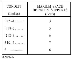
Figure 5-53.- Conduit support fastening. Table 5-5.- Nonmetallic Conduit Support
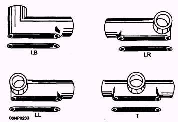
The number of supports needed depends on the type of conduit being used. Holes, or notches, in framing members may serve as supports. EMT and IMC require supports within 3 feet of each outlet box, junction box, cabinet, or fitting, and every 10 feet thereafter. Rigid metal conduit must also be supported within 3 feet of a box, but the distance between supports may be increased as the size of the conduit increases if the run is straight and is made up with threaded couplings. The distance between supports on direct vertical runs of rigid conduit from machine tools, and the like, may be increased to 20 feet if threaded couplings are used and the riser is supported at each end. Rigid nonmetallic conduit must be supported, as shown in table 5-5. In addition, it must be supported within 3 feet of each opening. Flexible metal conduit and liquidtight flex must be supported at intervals not to exceed 4 1/ 2 feet and within 12 inches on each side of every outlet box or fitting. Exceptions to this rule are runs of 3 feet or less where flexibility is needed or 6 feet where light fixtures are being connected. When you run conduit from one point to another, you often need to make more turns than the NEC(c) allows in a single run (360 of bends). When this larger number of turns is the case, you can use a fitting called a conduit body. Conduit bodies are often referred to by their brand names, such as Condulet or Unilet. A conduit body is a portion of a conduit system that provides access to the system through a removable cover to the interior of that system at a junction of two or more sections or at a terminal point. An important point to remember is that all Condulets must be accessible after construction is completed. Figure 5-54 shows some of the more common conduit bodies and covers.
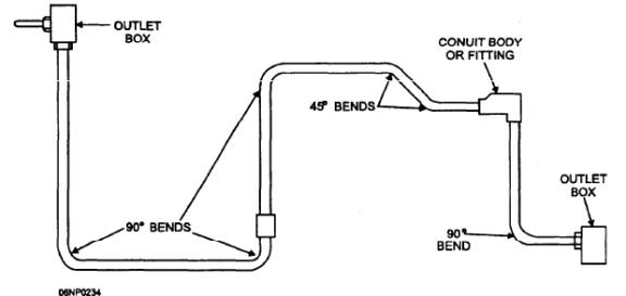
Figure 5-54.- Conduit bodies and covers. Figure 5-55 shows how a conduit body is put in conduit between two outlets to keep the bends within NEC(c) limits for a single run. As you can see, the run on the left has bends that total 360 degrees, which is all the NEC(c) permits. Thus a conduit body, as discussed in NEC(c) Article 300, had to be installed so that the conduit could be continued to the box on the right. After all conduit has been installed, supported, and connected to the boxes, you are ready to install the wire. Conductor installation into conduits is the same for all types of conduit. The most common type of wire used is TW. This letter designation simply means that the wire or conductor has thermoplastic, moisture-resistant insulation. When you are determining the length of wire needed to be pulled into the circuit, simply add the following: (1) lengths of conduit, (2) the size and number of boxes you must pull through, (3) the length of wire needed at each box, and (4) the makeup for the distribution panel. For short conduit runs with only two wires, the conductors can be pushed through the conduit from one box to the next. When the conduit has several bends and more than two conductors will be installed, a fish tape has to be used to pull the wires through the conduit. The fish tape normally has a hook on one end, which is pushed through the conduit. The hook also makes it easier to push the tape through. If the hook is broken off, you can make a new one with a pair of pliers and a propane torch. The torch is used to heat the end of the tape to take out the temper. On a l/ S-inch tape, heat
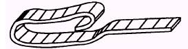
Figure 5-55.- Conduit body installed. 5-29 163
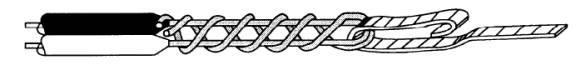
Figure 5-56.- Fish-tape hook. about 3 inches at the end of the tape until it is red-hot, and bend a hook on it about an inch long, like that shown in figure 5-56. This shape of hook seems to work best. After the hook is formed, reheat the end of the tape until it is red. Allow the end to cool until it becomes straw-colored. Then plunge it into a can of water until it is cool. This process restores the temper to the hook area. Once you have the fish tape in the conduit, attach the hook to the wires to be pulled, as shown in figure 5-57. Remove 4 to 6 inches of the insulation from the ends of the wires and thread the ends through the hook in opposite directions; bend them back and twist them around each other; then tape the hook and bare conductors to strengthen the attachment and make pulling easier. Use just enough tape to cover the hook and wires. Wire pulling usually takes two people-one to pull the fish tape and the other to feed the conductors into the conduit. The fish tape should be fed into the end of the conduit run from which it will be easiest to pull. It is usually best to pull the conductors from the distribution panel to the first box in the run, especially if the panel is energized. This procedure prevents your having to pull on the steel tape near an energized bus. WARNING Whenever conductors are being pulled into energized panels, be careful to keep clear of the bus bars. All energized parts should be covered with a rubber blanket. When several conductors must be fed into a conduit, you should keep them parallel, straight, and free from kinks and bends. Wires that are allowed to cross each other form a bulge and are hard to pull around bends. Whenever possible, feed conductors downward; for example, from the second floor to the first, so the weight of the wires will help in the pulling process. Another way to ease the pulling of conductors is to rub an approved lubricant, such as soap, talc, soapstone, or other noncorrosive substance, onto the insulation or blow it into the conduit. You may find that it is hard to keep the fish tape from slipping in your hands when you are pulling long runs or runs with several bends. When slipping is a problem, you can use the back side (insulation crushing point) of a pair of side-cutting pliers to grip the tape to give you a good pulling handle. Remember to leave at least 6 inches of free conductor at each outlet and switch box to make up splices or to connect devices. Conductors that are not spliced or connected to a device can be pulled directly through the box. The number of conductors you can have in conduit is based on the size of the conduit, the type of conductor insulation, and the size of the conductors. The NEC(c), chapter 9, has several tables to help you determine how many conductors of a certain size and insulation type you can have in a given size of conduit. These tables are based on fill; that is, the cross-sectional area of the conductors inside the conduit can take up only a certain percentage of the free space inside the conduit. You must use these tables whenever there is a question on the number of conductors to be pulled. Too many conductors in a conduit cause overheating, which reduces conductor ampacity. Once you have installed the conductors and all other finish work is complete, you are ready to do the electrical finish part. Finish work for conduit installations is the same as that for NM cable installations, which was covered previously in this chapter.
Figure 5-57.- Wires attached to fish tape.
|
|
|
|