Custom Search
|
|
  |
|
|
OFFSET BENDS.- An offset bend is two equal bends in opposite directions. It is used to avoid contacting a part of the structure or to bring the conduit out from the structure to match a knockout in a box or panel. The angle of the bend in an offset depends on several things; how much offset is needed, how much room there is where the offset is going to be placed, and the type of obstacle you are
avoiding. Figure 5-45 shows a box offset into a handy box. There is no way to mark the conduit for a box offset. The amount of bend and the distance between bends are estimated. The key to making good box offsets is practice.
Figure 5-46.- Bending an offset.
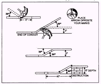
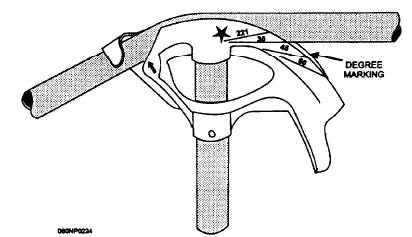
Figure 5-47.- Bender degree markings. To make accurate offsets of 2 inches or more in depth, you can mark a predetermined distance on the conduit. The distance between the bends depends on the depth of the offset and the amount of bend that you are going to use. Table 5-3 shows the formula to use to find the distance to be marked on the conduit. It also shows the constant multiplier that must be used in the formula for the angle of bends you intend to use and the shrinkage per inch. Let us use an example to see how the formula works. Suppose you need to avoid a part of a obstruction that requires an 8-inch offset, you are going to use 30-degree bends, and you are 40 inches from the obstruction. Table 5-3 shows that the constant multiplier for 30-degree bends is 2 and the shrinkage of one-fourth inch equals 2 inches for a total of 42 inches. Using the formula, multiply the depth of the offset (8 inches) times the constant multiplier (2), and the result is the distance needed between the bends (16 inches). You place the first mark at 42 inches, the second 16 inches apart, and using the arrow of the bender, make a 30-degree bend on the same side of each mark, as shown in figure 5-46. In this example, a 30-degree bend gives us the offset we need. If you make both bends inside the marks, you will end up with much less than the desired offset. If you make both bends outside the marks, you will have too much offset. The amount of bend, in this case 30-degree at each mark, is obtained by using the degree markings on the bender, as shown in figure 5-47. Notice that the side of the conduit closest to the bender is in line with the 30-degree marking on the bender. If you have a bender without markings, a protractor (works especially well on larger conduit) can be used or you can lay a 30-degree angle out on a large piece of paper or on the floor with chalk. Then check the bend against the 30-degree angle you have laid out. Normally, offsets are made by making the first bend on the floor and the second bend in the air, as shown in figure 5-48.
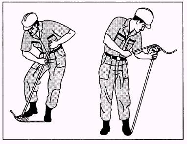
Figure 5-48.- Bending on the floor and in the air.
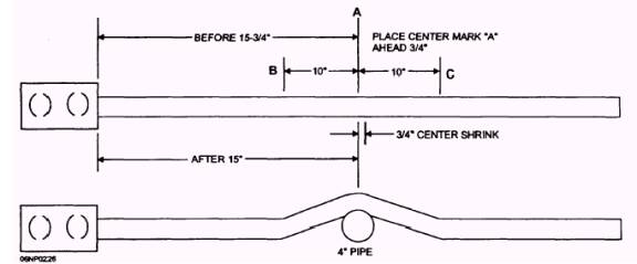
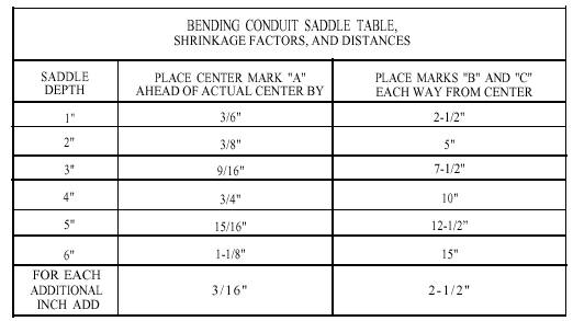
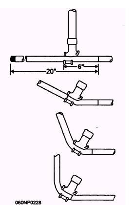
Figure 5-49.- Bending a conduit saddle bend. SADDLE BENDS.- Saddles may be necessary when obstructions (fig. 5-49) are encountered. The most common method of straddling an obstacle is the three-bend saddle, using a 45-degree center bend and two opposing 22 1/ 2-degree bends. All measurements begin with locating the center of the obstruction on the conduit and marking it as Point A. Table 5-4 shows shrinkage factors and distances for marks "B" and "C." The formula is from mark "A," add 3/ 16 of an inch times saddle depth and distance from mark "A" to marks "B" and "C" = 2.5 inches times saddle depth. Figure 5-49 is an example of placing a 4-inch saddle around a conduit that is 15 inches from a junction box. Following the bending sequence shown, pay close attention to the orientation of the bender head. Remember to use the star arrow on the bender to align Point A for the 45-degree center bend and the front arrow to align the bender with marks "B" and "C" for the 22 1/ 2-degree bends. Be sure to line up all bends in the same plane. This procedure is true of all bends, not just a saddle. Table 5-4.- Bending Conduit Saddle Table, Shrinkage Factors, and Distances
BENDING CONDUIT SADDLE TABLE, SHRINKAGE FACTORS, AND DISTANCES SADDLE PLACE CENTER MARK "A" DEPTH AHEAD OF ACTUAL CENTER BY PLACE MARKS "B" AND "C" EACH WAY FROM CENTER 1" 3/ 6" 2-1/ 2" 2" 3/ 8" 5" 3" 9/ 16" 7-1/ 2" 4" 3/ 4" 10" 5" 15/ 16" 12-1/ 2" 6" 1-1/ 8" 15" FOR EACH ADDITIONAL 3/ 16" 2-1/ 2" INCH ADD 06NP0227 Rigid Metal Conduit The procedures for making the different types of bends discussed thus far have all been with a one-shot bender. The same bends can be made with rigid conduit. Ahickey bender can be used on rigid metal conduit also although the procedures are slightly different. For instance, to make a 90-degree bend in 1/ 2-inch rigid metal conduit, you should take the steps shown in figure 5-50. Let us say you need a 20-inch stub-up at the end of the 1/ 2-inch stick of rigid conduit. The steps for bending with a hickey are as follows: Mark off 20 inches from the end of the conduit. Determine the take-up for 1/ 2-inch rigid conduit. (See table 5-2.) Make a second mark 6 inches back toward the end of the conduit. Place the hickey at the second mark and pull about 30 degrees of bend. Move the bender toward the 20-inch mark about 2 inches. Pull another 30 degrees of bend. Move the bender to where the heel of the bender is on the 20-inch mark and complete the 90- degree bend.
Figure 5-50.- Bending a 90 with a hickey.
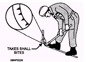
Figure 5-51.- Bending with a hickey using small bites. Since the hickey bender does not usually have degree markings on it, you have to estimate the amount of bend you are making with each bite. Small bites, as shown in figure 5-51, reduce the possibility of crimping or kinking the conduit. Mechanical Benders Mechanical benders are designed to bend conduits using a built-in ratchet for fast, no kink, bends. Depending on the make and model, they are portable and easy to use. Equipped with different shoe sizes, they will bend EMT conduit from 3/ 4 inch through 2 inch, rigid and aluminum conduit 1/ 2 through 1 1/ 2 and IMC 1/ 2 through 1 1/ 4. Minimum stub lengths and take-up deductible inches vary from the hand benders just discussed. While the bending principles are the same, you will need to check with the manufacturers directions and bending charts.
|
|
|
|