Custom Search
|
|
  |
|
|
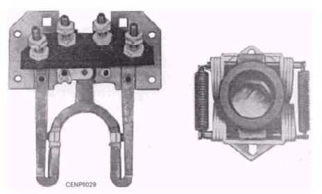
AC MOTORS Most of your work with motors, at shore stations especially, will be with a-c motors. Dc motors have certain advantages but a-c power is more widely used and a-c motors are less expensive and on the whole, more reliable. For example, sparking at the brushes of a dc motor can be very dangerous if there is explosive gas or dust in the surrounding air. On most a-c motors, brushes and commutators are not used and little maintenance is required. They are suited to constant speed applications and are designed to operate at a different number of phases and voltages. A-c motors are designed in various sixes, shapes, and types such as the induction, series, and synchronous, but as a Construction Electrician in the U. S. Navy, you will be concerned primarily with the induction motors. This type of motor includes, among others, the split-phase, capacitor, repulsion-induction, and the polyphase motors. SPLIT-PHASE MOTORS A split-phase motor is usually of fractional horsepower. It is used to operate such devices as small pumps, oil burners, and washing machines. It has four main parts. These are the rotor, the stator, the end plates (or end bells, as they are sometimes called), and a centrifugal switch The rotor consists of three parts. One of these parts is the core which is made up of sheets of sheet steel called laminations. Another part is a shaft on which these laminations are pressed. The third part is a squirrel-cage winding consisting of copper bars which are placed in slots in the iron core and connected to each other by means of copper rings located on both ends of the core. In some motors the rotor has a one-piece cast aluminum winding. The stator of a split-phase motor consists of a laminated iron core with semiclosed slots, a steel frame into which the core is pressed, and two windings of insulated copper wire that are placed into the slots and are called the running and starting windings. End bells, which are fastened to the motor frame by means of bolts or screws, serve to keep the rotor in perfect alignment. These end bells are equipped with bores or wells in the center, and are fitted with either sleeve or ball bearings to support the weight of the rotor and thus permit it to rotate without rubbing on the stator. The centrifugal switch is located inside the motor on one of the end bells. It is used to disconnect the starting winding after the rotor has reached a predetermined speed, usually 75 percent of the full load speed. The action of the centrifugal switch is as follows: the contacts on the stationary part of the switch (the stationary part is mounted on the end bell) are closed when the motor is not in motion and make contact with the starting winding. When the motor is energized and reaches approximately 75 percent of full load speed, the rotating part of the switch (mounted on the rotor) is forced by centrifugal force against the stationary arm, thereby breaking the contact and disconnecting the starting winding from the circuit. The motor is then operating on the running winding as an induction motor. Figure 7-29 shows the two major parts of a centrifugal switch.
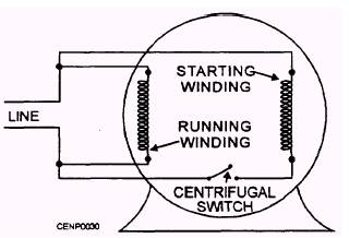
Figure 7-29.- Two major parts of a centrifugal switch. The direction of rotation of a split-phase motor may be reversed by reversing the connections leading to the starting winding. This action can usually be done on the terminal block in the motor. Figure 7-30 shows a diagram of the connections of a split-phase motor. Troubleshooting and Repair Motors require occasional repairs, but many of these can be eliminated by following a preventive maintenance schedule. Preventive maintenance, in simple terms, means taking care of the trouble before it happens. For example, oiling, greasing, cleaning, keeping the area around the equipment clean, and seeing that the equipment has the proper protective fuses and overload protection are preventive maintenance steps that eliminate costly repairs. To analyze motor troubles in a split-phase motor, the first check is for proper voltage at the terminal block. If you have the proper voltage, check the end bells for cracks and for alignment. The bolts or screws may be loose and the ends may be out of line. The next check is for a ground With the motor disconnected, check the connections from the terminal block to the frame with an ohmmeter or megger. If you find a ground in this test, remove the end bell with the terminal block and centrifugal switch and separate the starting winding and running winding and make another ground check on each of these windings. In many cases you will find the ground in the loops where the wires are carried from one slot to the next one. This situation can sometimes be repaired without removing the winding. In some cases, the ground may be in the centrifugal switch due to grease that has accumulated from over-greasing. If the first test does not show a ground in the motor, check to see that the rotor revolves freely. If the rotor turns freely connect the motor to the source of power
Figure 7-30.- Diagram of the connections of a split-phase motor. and again check to see that the rotor turns freely when energized. If the rotor turns freely with no voltage applied, but locks when it is applied, you will know that the bearings are worn enough to allow the iron in the rotor to make contact with the iron in the pole pieces. If the trouble is a short, either the fuse will blow or the winding will smoke when the motor is connected to the line. In either event the motor will have to be disassembled A burned winding is easily recognizable by its smell and the burned appearance. The only remedy is to replace the winding. If the starting winding is burned, it can usually be replaced without disturbing the running winding, but check closely to be sure that the running winding is not damaged. In making a check for a shorted coil, the proper procedure is to use an ohmmeter to check the resistance in the coil that you suspect to be bad. Then check this reading against a reading from a coil that is known to be good. An open circuit can be caused by a break in a wire in the winding, or by the centrifugal switch not closing properly when the motor is at a standstill. Too much end play in the rotor shaft may cause the rotating part of the centrifugal switch to stop at a point where it allows the contacts on the stationary part of the switch to stand open. Should the rotor have more than 1/ 64-inch end play, place fiber washers on the shaft to line the rotor up properly. If the motor windings are severely damaged, the motor must be sent to a motor shop for repairs. The repairs will usually be done in a shop operated by Public Works or the motor may be sent outside the base to a civilian operated motor shop. For this reason only the basic principles of the winding procedure will be covered.
Figure 7-31.- The pitch of a coil. Repair of a split-phase motor with a damaged winding consists of several operations: taking the winding data, stripping the old windings, insulating the slots, winding the coils and placing them in the slots, connecting the windings, testing, varnishing and baking the winding. Before the motor is taken apart, the end plates should be marked with a center punch so that they may be reassembled properly. One punch mark should be put on the front end plate and a corresponding mark made on the frame. Two marks should be made on the opposite end plate and also on the frame at that point. Taking the winding data is one of the most important parts of the operation This action consists of obtaining and recording information concerning the old winding; namely, the number of poles, the pitch of the coil (the number of slots that each coil spans), (fig. 7-31), the number of turns in each coil, the size of the wire in each winding, the type of connection (series or parallel), the type of winding, and slot insulation. See figure 7-32. This data is taken while removing the old winding from the motor frame. One coil should be cut at a place where the number of turns may be counted. The size of the wire and other data is then entered on the data sheet.
|
 |
|
|