Custom Search
|
|
  |
|
|
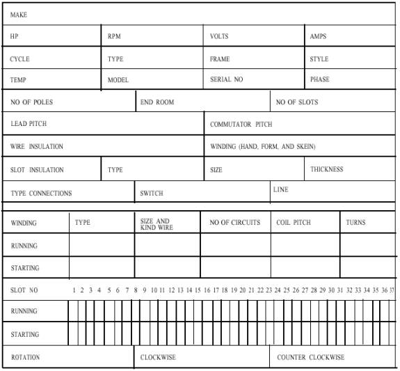
SPLIT PHASE MOTOR DATA
Figure 7-32.- Split-phase motor data sheet. Clean the old insulation and varnish from the slots before installing the new slot insulators. This cleaning is usually done with a torch. The slot insulators are formed from one of several types of material available for this purpose. The best procedure is to reinsulate the slots with the same type and size insulation that was used in the original winding. The coils are then wound according to the data sheet and replaced in the slots in the same position as the windings that were removed. The starting windings are ALWAYS placed 90 electrical degrees out of phase with the running windings. When all the connections between the poles of the windings have been completed and tested and the leads attached, the stator should be placed in a baking oven at a temperature of about 250 F and baked for three hours to remove any trace of moisture. Heating the windings also helps the varnish to penetrate the coils. The stator is then dipped in a good grade of insulating varnish, allowed to drip for about an hour and then placed in the oven and baked for several hours. When the stator is removed from the oven, the inner surface of the core of the stator should be scraped to remove the varnish so that the rotor will have sufficient space to rotate freely. Control for a Split-Phase Motor The control switch for a split-phase motor is usually a simple OFF and ON switch if the motor is equipped with an overload device. If the motor does not have this overload device, the switch will be of a type illustrated in figure 7-33. This type of switch has two push buttons; one to start and one to stop the motor. It uses interchangeable thermal overload relay heaters for protection of various size motors. In some cases, a 30- ampere safety switch with the proper size fuse may be used. CAPACITOR MOTORS The capacitor motor is similar to the split-phase motor, but an additional unit, called a capacitor, is connected in series with the starting winding, These motors may be of capacitor-start or the capacitor-run type. The capacitor is usually installed on top of the motor; but it may be mounted on the end of the motor
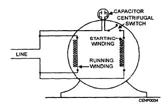
Figure 7-33.- Starting switch for a single-phase motor. frame, or inside the motor housing, or remote from the motor. Acapacitor acts essentially as a storage unit. All capacitors have this quality and all are electrically the same. The only difference is in the construction The type of capacitor usually used in fractional-horsepower motors is the paper capacitor. This type of capacitor has strips of metal foil separated by an insulator, usually waxed paper. The strips are rolled or folded into a compact unit which is placed in a metal container either rectangular or cylindrical in shape. 'Iwo terminals are provided for connections. The capacitor-start motor has, like the split-phase motor, a centrifugal switch which opens the starting winding when the rotor has reached the predetermined speed, while the capacitor-run motor does not have the centrifugal switch and the starting winding stays in the circuit at all times. Figure 7-34 shows a capacitor-start motor winding circuit. The capacitor motor provides a higher starting torque with a lower starting current than the split-phase motor.
Figure 7-34.- Capacitor start motor winding circuit. TROUBLESHOOTING AND REPAIR The procedure for troubleshooting and repair for the capacitor motor is the same as for the split-phase motor except for the capacitor. Capacitors are rated in microfarads and are made in various ratings, according to the size and type. Acapacitor may be defective due to moisture, overheating or other conditions. In such a case it must be replaced with another one of the same value of capacity. To test a capacitor, remove the motor leads from the capacitor and connect the capacitor in series with a 10-amp fuse across a 110-volt line. If the fuse burns out, the capacitor is short-circuited and must be replaced. If the fuse does not burn out, leave the capacitor connected to the line for a few seconds to build up a charge. Do not touch the terminals after the charging process as serious injury may result from the stored charge. Short the terminals with an insulated handle screw driver. A strong spark should show if the capacitor is good. If no spark or a weak spark results, the capacitor must be replaced. The procedure for rewinding a capacitor motor is the same as for the split-phase motor except for the capacitor.
|
 
|
|
|