Custom Search
|
|
  |
|
|
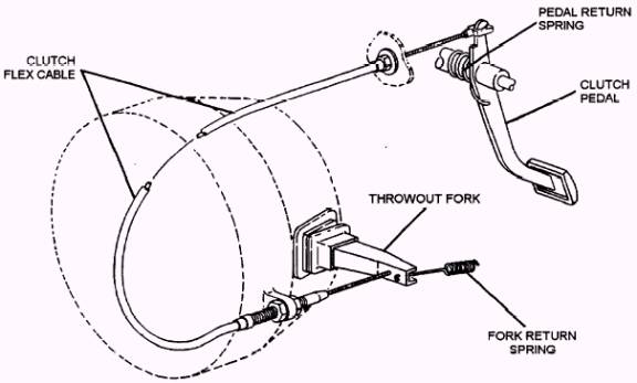
The clutch is the first drive train component powered by the engine crankshaft. The clutch lets the driver control power flow between the engine and the transmission or transaxle. Before understanding the operation of a clutch, you must first become familiar with the parts and their function. This information is very useful when learning to diagnose and repair the clutch assembly. Clutch Release Mechanism
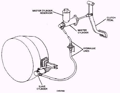
Figure 4-4.- Clutch cable mechanism. Movement of the clutch pedal creates hydraulic pressure in the master cylinder, which actuates the slave cylinder. The slave cylinder then moves the clutch fork. Clutch Fork A rubber boot fits over the clutch fork. This boot is designed to keep road dirt, rocks, oil, water, and other debris from entering the clutch housing. Release Bearing The release bearing snaps over the end of the clutch fork. Small spring clips hold the bearing on the fork. Then fork movement in either direction slides the release bearing along the transmission hub sleeve. Pressure Plate Clutch Housing The clutch housing is also called the bell housing. It bolts to the rear of the engine, enclosing the clutch assembly, with the manual transmission bolted to the back of the housing. The lower front of the housing has a metal cover that can be removed for fly-wheel ring gear inspection or when the engine must be separated from the clutch assembly. A hole is provided in the side of the housing for the clutch fork. It can be made of aluminum, magnesium, or cast iron. The pressure plate is a spring-loaded device that can either engage or disengage the clutch disc and the flywheel. It bolts to the flywheel. The clutch disc fits
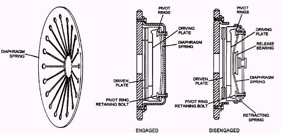
Figure 4-5.- Hydraulic clutch release mechanism. Coil spring pressure plate uses small coil springs similar to valve springs (fig. 4-6). The face of the pressure plate is a large, flat ring that contacts the clutch disc during clutch engagement. The backside of the pressure plate has pockets for the coil springs and brackets for hinging the release levers. During clutch action, the pressure plate moves back and forth inside the clutch cover. The release levers are hinged inside the pressure plate to pry on and move the pressure plate face away from the clutch disc and flywheel. Small clip-type springs fit around the release levers to keep them rattling when fully released. The pressure plate cover fits over the springs, the release levers, and the pressure plate face. Its main purpose is to hold the assembly together. Holes around the outer edge of the cover are for bolting the pressure plate to the flywheel. Diaphragm pressure plate (fig. 4-7) uses a single diaphragm spring instead of coil springs. This type of pressure plate functions similar to that of the coil spring type. The diaphragm spring is a large, round disc of spring steel. The spring is bent or dished and has pie-shaped segments running from the outer edge to the center. The diaphragm spring is mounted in the pressure plate with the outer edge touching the back of the pressure plate face. The outer rim of the diaphragm is secured to the pressure plate and is pivoted on rings (pivot rings) approximately 1 inch from the outer edge.
Figure 4-6.- Coil spring pressure plate.
Figure 4-7.- Diaphragm pressure plate operation. |
 |
|
|