Custom Search
|
|
  |
|
|
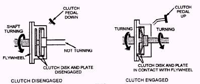
The clutch disc, also called friction lining, consists of a splined hub and a round metal plate covered with friction material (lining). The splines in the center of the clutch disc mesh with the splines on the input shaft of the manual transmission. This makes the input shaft and disc turn together. However, the disc is free to slide back and forth on the shaft. Clutch disc torsion springs, also termed damping springs, absorb some of the vibration and shock produced by clutch engagement. They are small coil springs located between the clutch disc splined hub and the friction disc assembly. When the clutch is engaged, the pressure plate jams the stationary disc against the spinning flywheel. The torsion springs compress and soften, as the disc first begins to turn with the flywheel. Clutch disc facing springs, also called the cushioning springs, are flat metal springs located under the friction lining of the disc. These springs have a slight wave or curve, allowing the lining to flex inward slightly during initial engagement. This also allows for smooth engagement. The clutch disc friction material, also called disc lining or facing, is made of heat-resistant asbestos, cotton fibers, and copper wires woven or molded together. Grooves are cut into the friction material to aid cooling and release of the clutch disc. Rivets are used to bond the friction material to both sides of the metal body of the disc. Flywheel Pilot Bearing The end of the transmission input shaft has a small journal machined on its end. This journal slides inside the pilot bearing. The pilot bearing prevents the transmission shaft and clutch disc from wobbling up and down when the clutch is released. It also assists the input shaft center the disc on the flywheel. CLUTCH OPERATION When the operator releases the clutch pedal, spring pressure inside the pressure plate pushes forward on the clutch disc (fig. 4-8). This action locks the
Figure 4-8.- Clutch operation. |
 |
|
|