Custom Search
|
|
  |
|
|
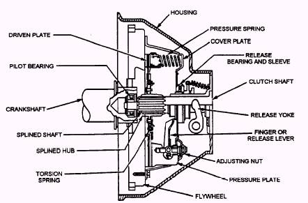
AUTOMOTIVE CLUTCHES, TRANSMISSIONS, AND TRANSAXLES INTRODUCTION AUTOMOTIVE CLUTCHES Learning Objective: State the operating principles and identify the components and maintenance requirements for an automotive clutch. In a vehicle, the mechanism that transmits the power developed by the engine to the wheels and/ or tracks and accessory equipment is called the power train. In a simple application, such as a stationary engine-powered hoist, a set of gears or a chain and sprocket could perform this task. However, auto-motive and construction equipment are not designed for such simple operating conditions. They are designed to provide pulling power, to move at high speeds, to travel in reverse as well as forward, and to operate on rough terrain as well as smooth roads. To meet these varying conditions, vehicle power trains are equipped with a variety of components. This chapter discusses the basic automotive clutch, transmissions (manual and automatic), and transaxles (manual and automatic). An automotive clutch is used to connect and disconnect the engine and manual (hand-shifted) transmission or transaxle. The clutch is located between the back of the engine and the front of the transmission. With a few exceptions, the clutches common to the Naval Construction Force (NCF) equipment are the single-, double-, and multiple-disc types. The clutch that you will encounter the most is the single-disc type, as shown in figure 4-1. The double-disc clutch (fig. 4-2) is substantially the same as the single disc, except that another driven disc and an intermediate driving plate are added. This clutch is used in heavy-duty vehicles and construction equipment. The multiple-disc clutch is used in the automatic transmission and for the steering clutch used in tracked equipment.
Figure 4-1.- Single-disc clutch.
A clutch linkage mechanism uses levers and rods to transfer motion from the clutch pedal to the clutch fork. One configuration is shown in figure 4-3. When the pedal is pressed, a pushrod shoves on the bell crank and the bell crank reverses the forward movement of the clutch pedal. The other end of the bell crank is connected to the release rod. The release rod transfers bell crank movement to the clutch fork. It also provides a method of adjustment for the clutch. The clutch cable mechanism uses a steel cable inside a flexible housing to transfer pedal movement to the clutch fork. As shown in figure 4-4, the cable is usually fastened to the upper end of the clutch pedal, with the other end of the cable connecting to the clutch fork. The cable housing is mounted in a stationary position. This allows the cable to slide inside the housing whenever the clutch pedal is moved. One end of the clutch cable housing has a threaded sleeve for clutch adjustment. |
 |
|
|