Custom Search
|
|
  |
|
|
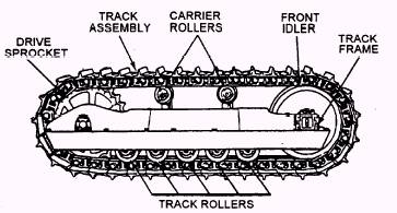
Learning Objective: Identify the operational components of the track and track frame. Describe the maintenance procedures used on tracks and track frame assemblies. The undercarriage of crawler-mounted equipment contains two major components- TRACK ASSEMBLY and TRACK FRAME. This under-carriage (fig. 6-18) is provided on equipment that must have positive traction to operate efficiently. TRACK ASSEMBLY Track Chain
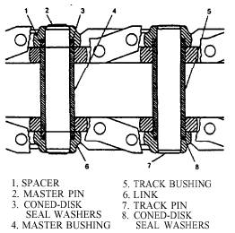
Figure 6-19.- Track chain cutaway. The pins and bushings wear much faster than other parts of the track because of their constant pivoting, as the track rotates around the track frame. This pivoting results in internal wear of both the pin and the bushing. As the pins and bushings wear, the track lengthens. When it does, the track is adjusted to remove excessive slack. Bushings that show lots of wear on the outside are good indicators of inner wear that is also nearing the maximum allowed by the manufacturer, if the track is to be rebuilt. To determine whether the track should be removed for rebuilding or replacement, measure the outside of the bushings and track "pitch" (length of the track). Use an outside caliper and ruler, as shown in figure 6-20. Measure the outside of the bushing where it shows the most wear and compare it to the manufacturer's specifications.
Figure 6-18.- Side view of crawler tractor chassis. Should the bushing wear or track length be excessive, remove the track for rebuilding unless facilities and time do not permit. Rebuilding a track will nearly double the useful life of the pin and bushings.
Figure 6-20.- Bushing wear measurement.
|
 |
|
|