Custom Search
|
|
  |
|
|
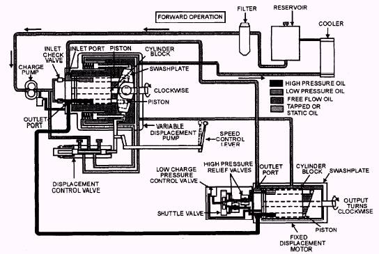
For you to understand how a hydrostatic drive operates, we will explain the operation of a typical system. The system we will use has an axial piston pump and motor which is the 'most common hydrostatic drive system. The pump has a variable displacement, while the motor has a fixed displacement. Now look at the complete system in operation- forward, neutral, and reverse. FORWARD (fig. 6-15).- When the operator moves the speed control lever forward, the spool in the displacement control valve, also known as the FNR valve (Forward, Neutral, and Reverse), moves from its NEUTRAL position. This action allows pressure oil to flow into the upper servo cylinder forcing the swash plate to tilt. Oil, expelled by the opposing servo cylinder. returns through the displacement control valve (FNR valve) to the pump case.
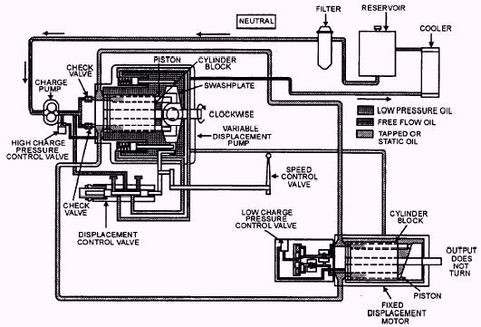
Figure 6-15.- Forward operation. As the swash plate reaches the tilt set by the speed control lever, the displacement control valve (FNR valve) spool returns to a NEUTRAL position, trapping the oil to both servo cylinders and holds the swash plate in its titled position. The swash plate will remain titled until the operator moves the speed control lever. With the pump drive shaft and cylinder block rotating clockwise and the swash plate is titled to the rear, it is now time to start pumping. As the cylinder rotates past the pump inlet port, the inlet check valve opens: oil is then forced by the charge pump into the piston bores that align with the inlet port under low charge pressure. As rotation continues, oil is forced out of the outlet port at high pressure by the pump pistons when they align with the outlet port. This flow of oil drives the motor. The distance the pistons reciprocate in and out of the cylinder block depends on the angle of the swash plate of the pump. This determines the volume of oil displaced per revolution of the pump. The greater the angle, the greater the volume and the more oil flows from the pump. As the angle of the swash plate is varied so will the volume of oil displaced from the pump. As pressure oil enters the inlet port of the motor, the pistons that align with the inlet port pushes against the swash plate. Since the fixed swash plate is always tilted, the pistons slide down the inclined surface and the resulting forces rotate the cylinder block. This, in turn. rotates the output shaft driving the machine forward. As the cylinder block continues to rotate clockwise, oil is forced out the outlet port at low pressure and returns to the pump where it is recirculated through the pump and back to the motor. This is called a "closed system" because the oil keeps circulating between the pump and the motor. The only extra oil comes from the charge pump that maintains a given flow of oil through the system whenever the machine is running. A shuttle valve, located in the motor manifold and controlled by high oil pressure, prevents high oil pressure from entering the low-pressure side of the system. This action keeps the charge circuit open to the low-pressure valve while the system is running. The high-pressure relief valve, located in the motor manifold, monitors the pressure of the forward flow of oil and protects the system from too high pressures. If pressure exceeds the rated psi, a relief valve opens and oil bypasses the cylinder block in the motor. This will either slow or stop the machine. The bypassed oil returns to the pump. This action continues until the load is reduced below the rated psi. Then the relief valve closes and oil again flows to the cylinder block, moving the machine forward. NEUTRAL (fig. 6-16).- With the speed control lever in neutral, free oil flows from the reservoir through the oil filter to the charge pump. The charge pump pumps the oil past the high charge pressure control valve and into the main pump housing. The oil circulates through the housing and returns through the oil cooler and back to the reservoir. Trapped oil is held in the cylinder block of the pump, in the motor, and in the connecting lines between the pump and motor by two check valves in the pump end cap. When the control lever is in neutral, the swash plate in the pump is also in neutral and the pistons within the pump are not pumping. Therefore no oil is being moved to provide either forward or reverse motion. The cylinder block in the pump rotates in a clockwise direction and is driven by the engine of the equipment. Rotation is viewed from the drive shaft end of the pump. Because the oil is not being pumped to the motor, the cylinder block in the motor is stationary and the output shaft does not move. NOTE With the drive system in neutral, the high charge pressure control valve, (located at the charge pump) controls pump pressure. When the system is activated for reverse or forward, the low charge pressure control valve located in the motor manifold controls the charge pressure at a lower psi. REVERSE (fig. 6-17).- As the speed control valve is moved to reverse, the spool in the displacement control valve (FNR valve) moves out of neutral allowing pressure oil to flow into the lower servo cylinder, tilting the swash plate forward. When the swash plate reaches its desired tilt, which is set by the control lever, the displacement control spool returns to neutral. This action traps the
Figure 6-16.- Neutral operation.
With the swash plate tilted forward and the pump drive shaft and cylinder block rotating clockwise, the ports reverse and the inlet port becomes the outlet and the outlet port becomes the inlet. As the pump cylinder block rotates past the pump inlet port, a check valve opens and oil is forced by the charge pump into the piston bores that align with the inlet port of the pump. As rotation continues, the oil is pressurized and forced out of the outlet port of the pump by each of the pistons, as they align with the outlet port. This action forces oil to flow to the motor, and as high-pressure oil from the pump enters the inlet port of the motor, the pistons are pushed against the swash plate. The pistons slide down the inclined surface of the swash plate, rotating the cylinder block. This action rotates the drive shaft counterclockwise, driving the piece of equipment in reverse. As the motor cylinder block continues to rotate, oil is forced out the outlet port at low pressure and returns to the pump. NOTE The PUMP DRIVE SHAFT and cylinder block always rotate clockwise, but the MOTOR DRIVE SHAFT and cylinder block rotate in clockwise and counterclockwise directions, depending on the direction of the oil entering the pump. Maintenance of Hydrostatic Drives Before removing any part of the system, ensure that the area is clean. Use steam-cleaning equipment if available; however, do NOT let any water into the system. Ensure that all hose and line connections are tight. If steam cleaning is not possible, diesel fuel or a suitable solvent may be used. Be certain to remove all loose dirt and foreign matter that may contaminate the system. Impurities, such as dirt, lint, and chaff, cause more damage than any one thing. Always seal openings when doing work to prevent foreign matter from entering the system. Clean the workbench or table before disassembling any hydrostatic system component for servicing. Be sure that all tools are clean and free of dirt and grease. NOTE NEVER perform internal service work on the shop floor or ground or where there is a danger of dust or dirt being blown into the parts. Before disassemble of any system component for internal service, certain items must be available. These items include the following: Clean plastic plugs of various sizes to seal the openings when removing hydraulic hoses and lines. Clean plastic bags to place over the ends of the lines and hoses. Secure the bags to the line and hoses with rubber bands. A container of solvent to clean internal parts. Ensure that all parts are clean before replacing them. Compressed air may be used to dry the parts after cleaning. A container of hydraulic fluid to lubricate the internal parts as they are reassembled. A container of petroleum jelly to lubricate surfaces where noted by the manufacturer during reassembly. Anytime the components are serviced and reassembled, always install new O rings, seals, and gaskets. This provides tight seals for mating parts and eliminates leakage. NOTE For instructions on the disassembly and reassembly of hydrostatic components, refer to the manufacturer's service manual. Never operate the hydraulic system empty. Always check the fluid supply after servicing the system. If fluid is to be added to the system. use ONLY the fluid recommended in the service manual. |
|
|
|