Custom Search
|
|
  |
|
|
BOMB EJECTOR RACKS LEARNING OBJECTIVE: Identify the purpose and use of bomb ejector racks to include their principles of operation, maintenance requirements, and operational description.
Figure 10-11.-Aero 7A-5 ejector rack assembly. making it easier for you to load the weapon. Inspection windows, one over each pair of suspension hooks, let you visually check sear engagement of the suspension hooks. Before you let go of the weapon or store when loading, check the inspection windows over the suspension hooks; the hooks must be locked. If the suspension hooks aren't properly engaged by the sear, the inspection window is blank. If the suspension hooks are properly engaged by the sear, you will see a horizontal black line (fig. 10-12) in the inspection window. The 14-inch suspension hooks allow a maximum weapon/store capacity of 1,500 pounds. The 30-inch suspension hooks allow a maximum weapon/store capacity of 3,500 pounds. The dual breech assembly accommodates two impulse cartridges. It consists of a cylinder, piston, foot ejector sleeve, and an ejector foot. After a weapon or store is loaded, you must adjust the ejector foot flush with the skin of the weapon or store, and then back it off to the first detent. You must never adjust the ejector foot lower than the black scribed line on the foot ejector sleeve, or you will damage internal components. The mechanical linkage allows the locking or releasing of the suspension hooks. You can manually release the suspension hooks by rotating the 3/4-inch manual release nut (located on the forward left-hand side of the bomb ejector rack) counterclockwise.
Figure 10-12.-Aero 7A-5 and Aero 7B-4 bomb ejector rack sear indicators
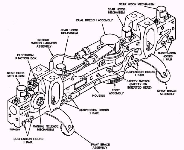
Figure 10-13.-Mk-39 electric fuze arming connector used on the Aero 7A-5 bomb ejector rack. Rotating the manual release nut mechanically actuates the mechanical linkage. This raises the suspension hook sears and opens the suspension hooks. The mechanical linkage is also activated by the dual breech assembly. The electrical junction box electrically connects the bomb ejector rack to the aircraft's weapons control system. Electrical power is supplied from the aircraft through the electrical junction box. This operates the mechanical arming solenoids, the dual breech assembly, and provides emergency operation of the rack. The voltage required for electrical arming doesn't pass through the electrical junction box. A separate connector assembly is located on the side of the bomb ejector rack. It connects the Mk 39 electric fuze connector to the aircraft's fuze function control system. The Aero 7A-5 has mechanical and electrical arming capabilities. Two electromechanical solenoids are attached to the bomb ejector rack. They give the pilot the in-flight option of selecting nose only, tail only, or nose and tail arming capabilities. When an armed drop of an electrically fuzed weapon is desired, the Mk 122 Mod 0 safety arming switch is installed in the weapon. It is electrically connected to the Mk 39 electric fuze arming connector (fig. 10-13) during weapon loading procedures. By using the Mk 122 Mod 0 safety arming switch, the weapon is free of the suspension hooks before forwarding the fuze arming signal to the electric fuze. Aero 7B-4 Bomb Ejector Rack The Aero 7B-4 bomb ejector rack (fig. 10-14) is similar in operation to the Aero 7A-5 bomb ejector rack. The Aero 7B-4 bomb ejector rack is 2 inches shorter in height than the Aero 7A-5. This, together with modifications in the aircraft keel, provides 4 inches of additional deck clearance at the centerline fuselage station on the A-6 aircraft. The side location of the dual breech assembly and the rack mounting method also differ from the Aero 7A-5.
Figure 10-14.-Aero 7B-4 bomb ejector rack. Principles of Operation Operation of the bomb ejector rack is initiated when 28-volt dc is applied to the two impulse cartridges installed in the dual breech assembly. The two impulse cartridges are fired simultaneously, creating gas pressure in the breech. Gas pressure buildup causes the breech and sleeve assembly, through the mechanical linkage, to raise the hook sears, which opens the suspension hooks. At the same time, gas pressure is applied to the piston assembly to drive the ejector foot downward and eject the store from the bomb ejector rack. After ejection, a spring in the sleeve assembly returns the ejector foot to the sleeve housing. Emergency operation of the rack is identical to normal operation, except that completely separate electrical wiring is used for each impulse cartridge to ensure detonation of the two impulse cartridges. Mechanical arming is done through the electromechanical arming solenoids. It works in the same manner as the Aero 65A series bomb racks. When an armed drop is to be made by using electric fuzing, an electrical signal is applied to the Mk 39 electric fuze arming connector. When the hooks open, this signal is transmitted to the Mk 122 Mod 0 safety arming switch, which arms the weapon as it clears the rack suspension hooks. You don't want the bomb ejector rack to fire during ground operations. To prevent firing, insert a safety pin into the safety switch assembly. The safety pin maintains an open firing circuit, grounds the breech cap assembly electrical circuit, and mechanically blocks the linkage to prevent the suspension hooks from opening manually. If the suspension hooks are opened manually, remove the safety pin. If you rotate the manual release nut with the safety pin installed, you will damage the linkage and possibly shear a sear retainer pin. Once the hooks are manually opened, you can reinstall the safety pin to load weapons or stores. Maintenance Requirements Organizational-level maintenance for the Aero 7A-5 and the Aero 7B-4 bomb ejector racks is normally performed while the bomb ejector racks are installed on the aircraft. The exception is the 21-day special inspection. In this case, the bomb ejector rack is removed from the aircraft. The bomb ejector racks are also removed from the aircraft and routed to an intermediate-level maintenance activity every 420 days for rework. They are removed from the aircraft every 42 months and routed to a depot-level maintenance activity for overhaul. Normally, routine maintenance at the organizational level is performed during regularly scheduled servicing intervals. Servicing intervals are classed as daily inspections, loading inspections, turnaround inspections, special inspections, and inspections performed after five firings or at the end of a firing day, whichever occurs first. A few of the more common organizational maintenance requirements are discussed in the following paragraphs. |
|
|
|