Custom Search
|
|
  |
|
|
Ejector Mechanism Cleaning and Inspection You must remove the bomb ejector mechanism from the bomb ejector rack for cleaning and inspection after every five shots or at the end of a firing day, whichever occurs firsto
Figure 10-15.-BRU-10A/B bomb ejector rack. Once the parts have been properly cleaned, you should inspect them for damage or wear and replace or repair the parts as necessary. Before reassembling the ejector mechanism, apply a light coat of generalpurpose preservative lubricating oil (VV-L-800). To prevent the piston from locking up, you must wipe off all the excess oil. For further information concerning the Aero 7A-5 and Aero 7B-4, refer to the publication Ejector Rack Assembly Model Aero 7A-5, NAVAIR 11-5D-20. BRU-10A/B AND BRU-11A/A BOMB EJECTOR RACKS The BRU-10A/B and BRU-11A/A bomb ejector racks are used to mount and sway brace a single weapon/store or for a variety of multiple weapon/store adapters. The BRU-10A/B bomb ejector rack is pylon mounted on the wing stations of the A-7E aircraft. It is part of the aircraft's basic weapon/store suspension system. It may also be weapons-rail mounted to the F-14 aircraft fuselage. The BRU-11A/A bomb ejector rack is pylon mounted on the wing stations of the S-3 aircraft. It is part of the aircraft's basic weapon/store suspension system. BRU-10A/B Bomb Ejector Rack The BRU-10A/B bomb ejector rack (fig. 10-15) has four suspension hooks-two hooks spaced 14 inches apart and two hooks spaced 30 inches apart. It carries weapons/stores weighing up to 4,000 pounds. The bomb ejector rack has the necessary electrical connections, mechanical and electrical arming units, ejection components, and the mechanical linkage for safely suspending and ejecting weapons or stores. Although the BRU-10A/B bomb ejector rack differs from the bomb ejector racks previously discussed, the basic principles of operation are the same, except for the operations discussed in the following paragraphs. As you read them, refer to figure 10-15. A manual cocking bolt and a manual release bolt are located on the forward left-hand side of the frame assembly, Before you load a weapon or store, manually cock the mechanical linkage by rotating the cocking bolt. This places the linkage sears in a position to lock the suspension hooks when they are moved to the closed position. The suspension hooks may be released (opened) by manually rotating the manual release bolt. To prevent damage to the mechanical linkage, you must remove the safety flag assembly (safety pin) before you rotate either the cocking bolt or the release bolt.
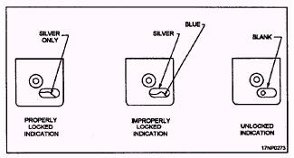
Figure 10-16.-BRU-10A/B bomb ejector rack hook latched indicators. To find out if the suspension hooks are properly Iocked, you must visually check the latch inspection holes (fig. 10-16) located in the frame assembly above each hook. If the hook is properly locked, you can see a silver latch indicator through the latching inspection hole. If the hook is not locked, you can see a blue or silver latch indicator. If the hooks are unlocked (open), the latching inspection hole will be blank. The BRU-10A/B bomb ejector rack is designed to hold one ejector assembly that can be inserted in the bomb rack in one of four different positions (fig. 10-17).
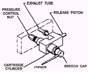
Figure 10-17.-BRU-10A/B bomb ejector rack ejector assembly and installation positions. The position depends on the aircraft and the weapon/store requirements. For ease of removal and installation, the ejector assembly is secured in the bomb rack by a quick-release LOK pin assembly. The release piston (fig. 10-18) is operated by gas pressure. It is used to actuate the mechanical release linkage during cartridge ejection, and to unlock the suspension hooks. A properly installed safety pin assembly safes the bomb ejector rack mechanically by blocking the mechanical release linkage. Although the safety flag assembly does not safe the rack electrically, it does prevent ejection of loaded weapons/stores if the cartridges are accidently fired. When the safety flag assembly is inserted in the bomb rack, the safety pin depresses the relief linkage assembly. The relief linkage assembly then depresses one of the two breech relief valves (fig. 10-17) to vent gases if a cartridge is accidently fired. The relief linkage assembly is arranged so that one of the breech relief valves is depressed regardless of which position the ejector assembly is actually installed in the bomb rack. The BRU-10A/B bomb ejector rack has an auxiliary release unit assembly. It provides an emergency method of release if the ejector assembly or its electrical system should fail. The BRU-10A/B bomb ejector rack auxiliary release unit assembly (fig. 10-18) consists of a pressure control nut, exhaust tube, release piston, breech cap, and a breech cylinder. When the separation cartridge is fired, the expanding gases supply the force to actuate the release piston. The release piston extends to actuate the mechanical release assembly, releasing the suspension hooks. The suspension hooks release the weapon/store. The auxiliary release unit assembly does not eject the weapon/store. If a cartridge in the auxiliary release unit assembly is accidentally fired, the installed
Figure 10-18.-BRU-10A/B bomb ejector rack auxiliary release unit assembly. safety flag assembly prevents movement of the mechanical release mechanism assembly. The gas pressure generated by the ignition of the cartridge vents to the atmosphere through an exhaust tube on the auxiliary release unit assembly. Organizational-level maintenance is limited to cleaning, replacing, and corrosion control of damaged parts and assemblies that can be replaced without removal of the bomb rack from the aircraft. If a BRU-10A/B bomb ejector rack requires inspection or repair beyond the scope of the organizational maintenance level, route the bomb rack to the intermediate or depot maintenance level. A few of the routine maintenance requirements are discussed in the following paragraphs. After every five firings or at the end of the day's operation, whichever occurs first, the ejector assembly must be removed from the bomb ejector rack for cleaning and inspection. The actual cleaning and inspection requirements are the same as for the bomb ejector racks previously discussed. After the ejector assembly has been disassembled, cleaned, and inspected, you should lubricate the parts with a thin coat of MIL-L-19701 lubricant prior to reassembly. |
 
|
|
|