Custom Search
|
|
 
|
||
|
Refer to figure 13-3 to help clarify how a video camera operates. In the video camera, an image (a) is gathered by the camera lens (b), and focused on the face of the camera pickup tube (photocathode) or a solid-state imaging device (c). The face or screen of the photocathode is covered with thousands of light sensitive dots. As light from a particular part of the scene falls on each dot, the dot becomes electrically charged. A charge pattern is built up proportionally to the brightness of the scene. An electron beam in the pickup tube emits a steady beam of electron particles. This electron beam scans the charged pattern on the photocathode and reads over it in a series of lines. The scanning beam neutralizes each picture element or dot and produces varying electrical currents (the video signal). These currents are proportional to the charge pattern which are proportional to the light transmitted through the lens. The current or video signal (picture) is amplified (d) and then recorded on tape by rotating heads (e) and then converted back to visible screen images in the viewfinder (f). As each dot on the tube screen is scanned, the dot gives up its information and is wiped clean so the tube screen can respond to any new light it receives.
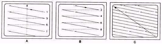
Figure 13-4. Video scanning.
Figure 13-4 illustrates how this scanning process takes place. The electron beam first scans all odd-numbered lines, from left to right (a). When all odd-numbered lines have been scanned, it makes up a field. One field consists of 262.5 lines. After the odd-numbered ones are scanned, the beam jumps back to the top of the screen. At this point, the beam is so weak that it does not affect the screen. Back at the top of the screen the beam starts scanning the even-numbered lines (b). When all even-numbered lines are scanned a second field is formed. The two fields make up a frame (c) or one complete television picture. A frame consists of 525 lines. After completing a frame, the beam returns to the top to start with another first field. This charge-forming-and-scanning is a fast, continuous process. The complete camera tube screen (frame) is scanned 30 times per second. The motion-video camera picks up reflections of light from the scene while the microphone picks up sound. At the same time, the camera changes the light reflections into electrical impulses, and the microphone changes the sound into electrical impulses. This is basically the way a black-and-white video camera works. A color video camera works on the same principle; however, a color video camera has three tubes. Through the use of a beam splitting device and filters, one tube forms a red image, a second tube forms a green image, and the third tube forms a blue image. The three tubes have identical scanning patterns, so the picture signals they produce are identical, except they differ in color. During a video recording, the videotape moves past a rotating head that writes the video and audio signals on the videotape. During playback, the rotating head reads the magnetically stored information off the tape Some VTRs use two or four heads for their record/play (write/read) functions. Digital VTRs have even more
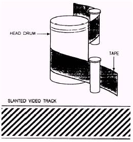
Figure 13-5. Helical scanning system. read/write heads. For explanation purposes a VTR with two record/play heads is discussed in this chapter. Helical, or Slant-Track, System The two heads are mounted opposite each other, either on a rapidly spinning head drum or on a bar that spins inside a stationary head drum. When the bar spins inside a stationary head drum, the heads contact the tape through a slot in the head drum. The tape is wound around the head drum in a slanted, spiral-like manner. This permits more tape area to contact the head, allowing the transfer of large amounts of video information (fig. 13-5). If the head contacted only the width of the tape, extreme tape or drum speed would be necessary. Because the Greek word for spiral is helix, this tape wrap, and often the whole video-recording system, is called the helical scan, or slant track
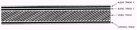
Figure 13-6. Basic videotape track system. Most videotape recorders put at least four separate tracks on the tape: the video track that contains the picture information, two audio tracks that contain all sound information, and a control track that controls the videotape and rotation speed of the video heads (fig. 13-6). VIDEO TRACK.-When video signals are recorded in the normal NTSC composite configuration, one pass of the head records a complete field of video information (Y+C). The next pass of the head, (or, if you have a two-head machine, the second head) lays down the second field right next to it, completing a single video frame. Two fields make up a single frame. The two heads must write sixty tracks (thirty frames) for each second of NTSC video. In the four-head VTR, one pair of heads records at normal tape speed and the other pair records at a slower speed. AUDIO TRACK.-The audio tracks record the audio signal. They are usually recorded by fixed recording heads that are near the edge of the tape and run along the length of the videotape. Because of the demand for stereo audio and for keeping certain sounds separate even in monophonic sound, all VTR systems provide at least two audio tracks. CONTROL TRACK.-The control track contains evenly spaced blips or spikes, called the sync pulse, that mark each complete television frame. These pulses synchronize the tape speed and the rotation speed of the recording heads. This allows the tape to be played on a similar machine without picture breakups. Because the control track marks each frame of recorded video, it also aids in videotape editing. Hi8 Track System Because space is so limited in 8mm videotape, these systems squeeze the automatically generated time code and other data between the video and audio portion of a single-slanted track The time code has been developed to provide a precise editing reference by recording the exact frame address onto the tape. The 8mm time code is digitally recorded by units of hour, minute, second, and frame by the video heads. The 8mm time code is used only for 8mm format and is not compatible with other recording formats. The Hi8 VTR splits each slanted track into audio frequency modulation (AFM) and video information. It also uses a pulse code modulation (PCM) audio track The audio technology used in an Hi8 VTR is superior to video home system (VHS). The video/AFM audio track and the PCM audio track are separated by the time-code data (fig. 13-7). |
 |
|
|
||