Custom Search
|
|
 
|
||
|
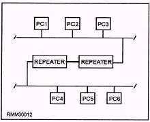
CHAPTER 2 LAN HARDWARE Upon completing this chapter, you should be able to do the following: l Explain how to install, inspect, and test network components. Describe how to make physical connections to networks. Explain the function of a network server. l l As noted in chapter 1, if the hardware, network software, application software, and cabling were all supplied by the same manufacturer, we would have relatively few problems to contend with when we design and implement a network. The answers to many hardware and software incompatibilities are found in the use of interfaces. These various types of interfaces (bridges, gateways, routers, and so on) allow networks to be compatible with one another. NETWORK COMPONENTS More and more, LANs are becoming part of larger networks. By connecting LANs together, any peripheral device, such as external hard disk, printer, or plotter can be shared by all users of the networks. This makes more efficient use of expensive peripherals. Repeaters can be used to amplify electrical signals; which, in turn, allows transmissions to travel greater distances. Bridges (also known as bridge servers) make it possible to interconnect like LANs; that is, two similar networks. Routers enable networks to communicate using the most efficient path. Brouters combine the functions of a bridge and a router. Gateways (also known as gateway servers) make it possible to interconnect unlike LANs; that is, two dissimilar networks. INSTALL COMPONENTS The installation of network components is dependent on the particular type of component, the manufacturer, and the type of cable being used. When it comes to installing one of these components, read the instructions that are supplied with the component to make sure that you install it properly. Repeaters Repeaters are used to amplify electrical signals carried by the network. They work at layer 1 of the OSI model\the physical layer. (The OSI model was covered in chapter 1.) The function of a repeater is to receive incoming signals (a packet of data), regenerate the signals to their original strength, and retransmit them. Repeaters are used to lengthen individual network segments to form a larger extended network. That is, repeaters allow a network to be constructed that exceeds the size limit of a single physical segment by allowing additional lengths of cable to be connected (see figure 2-l). There is a catch, however. For a repeater to be used, both network segments must be identical-same network protocols for all layers, same media access control method, and the same physical transmission technique. This means we could connect two segments that use the CSMA/CD access methods, or connect two segments that are running under the
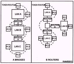
Figure 2-1.\Repeaters used to lengthen individual network segments. token-passing access method. However, we cannot connect a CSMA/CD segment to a token-passing segment. Bridges Bridges handle the first two layers of the OSI model\the physical layer and the data link layer. Like repeaters, bridges connect physically-isolated networks to forma single logical network; however, a bridge has a little more intelligence and can provide some translation between dissimilar protocols. For example, our token-passing segment wants to communicate with our CSMA/CD segment. The bridge will "repackage" the message from the token-passing segment into a format that the CSMA/CD segment will understand. Then, the bridge will act as a workstation on the CSMA/CD segment and contend for access. The same thing happens in reverse. A message is sent from the CSMA/CD segment to the token-passing segment. The bridge then "repackages" the message into a format the token-passing segment is expecting and waits for the token, just like any other workstation. An important point to remember is that a bridge will pass on any message it receives. Because the bridge is not smart enough to know that unlike LANs do not understand each other, it will go ahead and send the message. Because the two LANs speak a different "language," the message will be ignored. Routers Routers only connect networks running similar access methods. They work at the third layer of the OSI model\the network layer. Like bridges and repeaters, routers can connect networks over different wiring media and topologies. However, unlike bridges, routers can intelligently determine the most efficient path to any destination, based on predetermined delimiters. Routers are often a better choice for interconnecting remote installations and congested networks requiring a single protocol. Let's look at this more closely. Let's say we have a LAN made up of three token-passing segments, and each segment is connected via a bridge. For a message to go from LAN A to LAN C, it would have to travel through LAN A and LAN B before it reaches its final destination, which is LAN C. See figure 2-2, frame A. On a LAN that has large amounts of message traffic, we can see how a bridge may slow down the system. On the other hand, if the segments are separated by routers, the router on LAN A would look at the destination of the message and determine the direct route to LAN C that would be shortest route, as shown in figure 2-2, frame B. Brouters A brouter can work in either the second and third layers of the OSI model\the data link layer or the network layer. A brouter is a combination of a bridge and router combined. If it can't route a packet, it acts as a bridge. Brouters are particularly useful if you have two or more different networks. Working as a bridge, a brouter is protocol independent and can be used to filter local are a network traffic. Working as a router, a brouter is capable of routing packets across networks. Gateways Gateways work at OSI model layer 7\the application layer. A gateway functions to reconcile differences between two dissimilar networks. Messages are not only repackaged for transmission between different networks (CSMA/CD to token-passing), but the contents of the messages are converted into a format the destination can use and understand. Now our unlike LANs can talk to each other. Gateways can also provide links between microcomputer networks and mainframes. A gateway is generally a dedicated computer with an interface card and at least some type of software for both of the environments being connected. The gateway then runs special software that provides the necessary conversion and translation services which, in turn, allow the two environments to communicate.
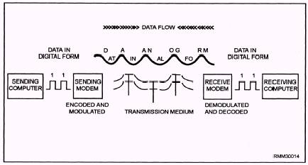
Figure 2-2.\Interconnecting LANS using (A) bridges and (B) routers. Concentrators The main function of a concentrator is to serve as a termination point for cable running from individual nodes in a network. The cable connects to the network or to another wire center. A concentrator may have multiple boards or boxes mounted on a rack. Each board is essentially a hub, a wiring center for a single network's nodes. Such boards generally include light-emitting diodes (LEDs) to indicate the status of each port on the board. Hubs A hub is a box with a number of connectors to which multiple nodes (PCs) are attached. It serves as a common termination point that can relay signals along the appropriate paths. All hubs provide connectivity, and some even provide management capabilities. A hub usually connects nodes that have a common architecture. Although the boundary between concentrators and hubs is not always clear, hubs are generally simpler and cheaper than concentrators. Modems In module 2, we introduced you to modems and how they are used in a data communications environment. They translate data from digital to analog form at the sending end of the communications path and from analog to digital at the receiving end. From a conceptual standpoint, this explanation is sufficient. However, if you are going to install a modem, you need to know some of the technical aspects of modems. MODEMS AT WORK.\ Put simply, the object of a modem is to change the characteristics of a simple sine wave, referred to as a carrier signal. We know this carrier signal has several properties that can be altered to represent data. It has amplitude (height); it has frequency (a unit of time); and it has phase (a relative starting point). Modems are capable of altering one or more of these characteristics to represent data. The job a modem performs can be divided into two discrete parts or phases at each end of the communications link. At the sending end, it converts digital bit streams (strings of 0's and 1's) into analog sine waves. This is the encoding process. Another component within the modem then changes (modulates) the analog signal so the data may be transmitted simultaneously with other data and voice traffic that has also been modulated. This process is basically reversed at the receiving end. There, the analog signal is brought back to its basic level (demodulated), and the analog sine waves are reconverted (decoded) back into their corresponding bit streams (see figure 2-3). CODECs.\ In today's digital communications lines, voice traffic is considered the outsider that digital data used to be to analog lines. Voice can enter the data communications lines only after being encoded into digital form. It then must be decoded to be audible again at the receiving end. The device used to perform the encoding and decoding functions is known as a codec. This is simply another black box conversion device that has always been in existence in a slightly different form as part of a modem.
Figure 2-3.\Digital data as it is encoded, modulated, transmitted, demodulated, and decoded. |
 |
|
|
||