Custom Search
|
|
 
|
||
|
Firing the M14 Rifle If the command does not desire automatic fire,, the selector on your rifle will be removed and a selector shaft lock is (see fig. 3-20) inserted so that the rifle is capable only of semiautomatic fire. For a rifle equipped with a selector shaft lock, simply push the safety forward and then fire a round with each squeeze of the trigger. For semiautomatic fire on a rifle equipped with a selector, position the selector for semiautomatic fire and then fire a round with each squeeze of the trigger. For automatic fire with a selector (rifle cocked), proceed as follows:
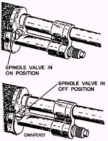
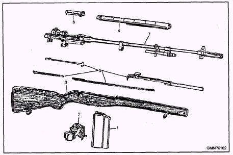
Figure 3-27.-Gas spindle valve in the ON and OFF positions. 1. Position the selector for automatic free. 2. Push the safety forward. 3. Squeeze the trigger. The rifle will fire automatically as long as the trigger is squeezed and there is ammunition in the magazine. Release the trigger to cease firing. 4. After the last round is fired, the magazine follower (a spring-driven plate in the magazine that forces cartridges upward as rounds are expended and cases ejected) actuates the bolt lock, locking the bolt in the rearward position. When an empty magazine is removed and a loaded one inserted, release the bolt lock by retracting the operating rod, thereby drawing the bolt rearward, then close the bolt. As the bolt assembly is closed, the top cartridge in the magazine is pushed forward into the chamber. Unloading the M14 Rifle To unload the M14 rifle, proceed as follows: 1. Push the safety to the SAFE (back) position. 2. Grasp the magazine with your thumb on the magazine latch, and squeeze the latch to release it. Push the magazine forward and downward to disengage it from the front catch, and then remove it from the magazine well, as shown in the right-hand view of figure 3-24. 3. Pull the operating rod handle all the way to the rear and lock it, using the bolt catch. 4. Inspect the chamber to make sure it is clear. The rifle is clear only when no round is in the chamber, the magazine is out, the safety is set (to the rear), and the bolt is in the REAR position. Field Stripping the M14 Rifle Figure 3-28 shows how the M14 rifle breaks down into seven group assemblies. You should be able to disassemble the rifle to this extent for cleaning, lubrication, and maintenance. This procedure is called field stripping the rifle. The names of the numbered group assemblies shown in figure 3-28 areas follows: 1. Magazine 2. Firing mechanism 3. Stock with butt plate assembly 4. Handguard assembly 5. Operating rod and connector group
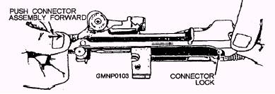
Figure 3-28.-Group assemblies of the M14 rifle. 6. Bolt assembly 7. Barrel and receiver group To withdraw the firing mechanism (No. 2 in fig. 3-28) from the stock, proceed as follows: 1. Remove the magazine. 2. Place the safety in the SAFE position after making sure the rifle is cocked. 3. Disengage the hooked end of the trigger guard from the firing mechanism housing. 4. Swing the trigger guard away from the stock (but do not rotate it more than 90 degrees), and pull straight away from the stock to draw out the firing mechanism. To remove a stock with a butt plate assembly after removing the firing mechanism, proceed as follows: 1. Separate the stock with a butt plate assembly from the rifle by grasping the receiver firmly with one hand and striking the butt of the stock sharply with the palm of the other. 2. Lift the stock from the barrel and receiver group. To separate the operating rod and connector group from the barrel and receiver group, proceed as follows: 1. Depress the rear sight to the lowest position and turn the barrel and receiver group on its side with the connector assembly upward 2. If the rifle has a selector, press in and turn the selector until the face marked "A' is toward the rear of the sight knob and the projection forward is at an angle of about 35 degrees. Then remove the connector assembly, as indicated in paragraphs 3 and 4. 3. If the rifle has a selector shaft lock, press forward on the rear of the connector assembly with your right thumb, as shown in figure 3-29, until the front end can be lifted off the connector lock.
Figure 3-29.-Disengaging the connector assembly. 3-19
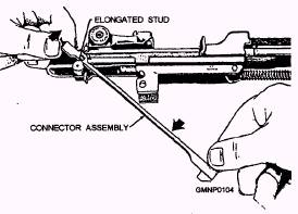
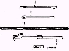
Figure 3-30.-Removing the connector assembly. 4. Rotate the connector assembly about 35 degrees clockwise until the slot at the rear is aligned with the elongated stud on the sear release (fig. 3-30); then lower the front end of the connector assembly and lift it off the sear release. The next step is to remove the operating rod spring guide, the operating rod spring, and the operating rod. These parts are identified as 2, 3, and 4, respectively, in figure 3-31. The correct step-by-step procedure is as follows: 1. with the barrel and receiver group upside down, pull forward on the operating rod spring, relieving pressure on the connector lockpin. Pull the lock outward to disconnect the operating rod spring guide. 2. Remove the operating rod spring guide and the operating rod spring. Turn the barrel and the receiver group right side up. 3. Retract the operating rod until the key on its lower surface coincides with the notch in the receiver.
Figure 3-31.-Component parts of the operating rod and connector group. Lift the operating rod free and pull to the rear, disengaging it from the operating rod guide. To remove the bolt after removal of the operating rod, grasp the bolt roller that engages with the operating rod and slide it forward. Lift upward and outward to the right with a slight rotating motion and remove the bolt from the receiver. The weapon is now field-stripped for cleaning. Reassembly of this weapon is basically the reverse of disassembly. A step-by-step procedure for reassembly and other maintenance procedures is covered in the U.S. Army FM 23-8. |
 |
|
|
||